Flexible printed wiring substrate
a flexible, printed substrate technology, applied in the direction of printed circuit aspects, printed element electric connection formation, high frequency circuit adaptation, etc., can solve the problem that a single flexible substrate cannot connect all the wires, and achieve the effect of reducing the occurrence of electrode displacement, high reliability, and advanced downsizing and high-density packaging of optical transmission modules
- Summary
- Abstract
- Description
- Claims
- Application Information
AI Technical Summary
Benefits of technology
Problems solved by technology
Method used
Image
Examples
embodiment 1
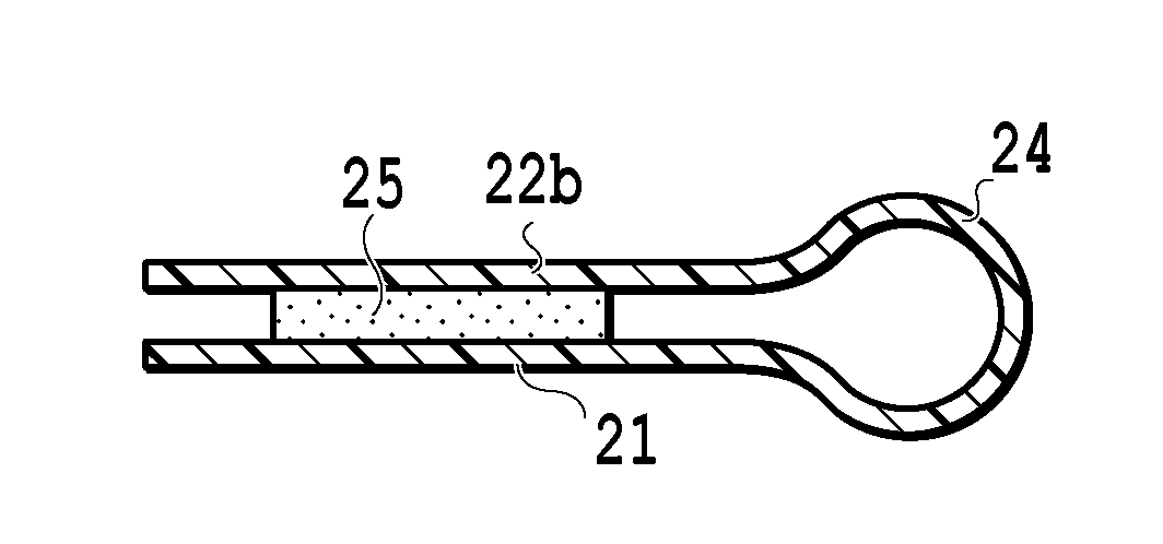
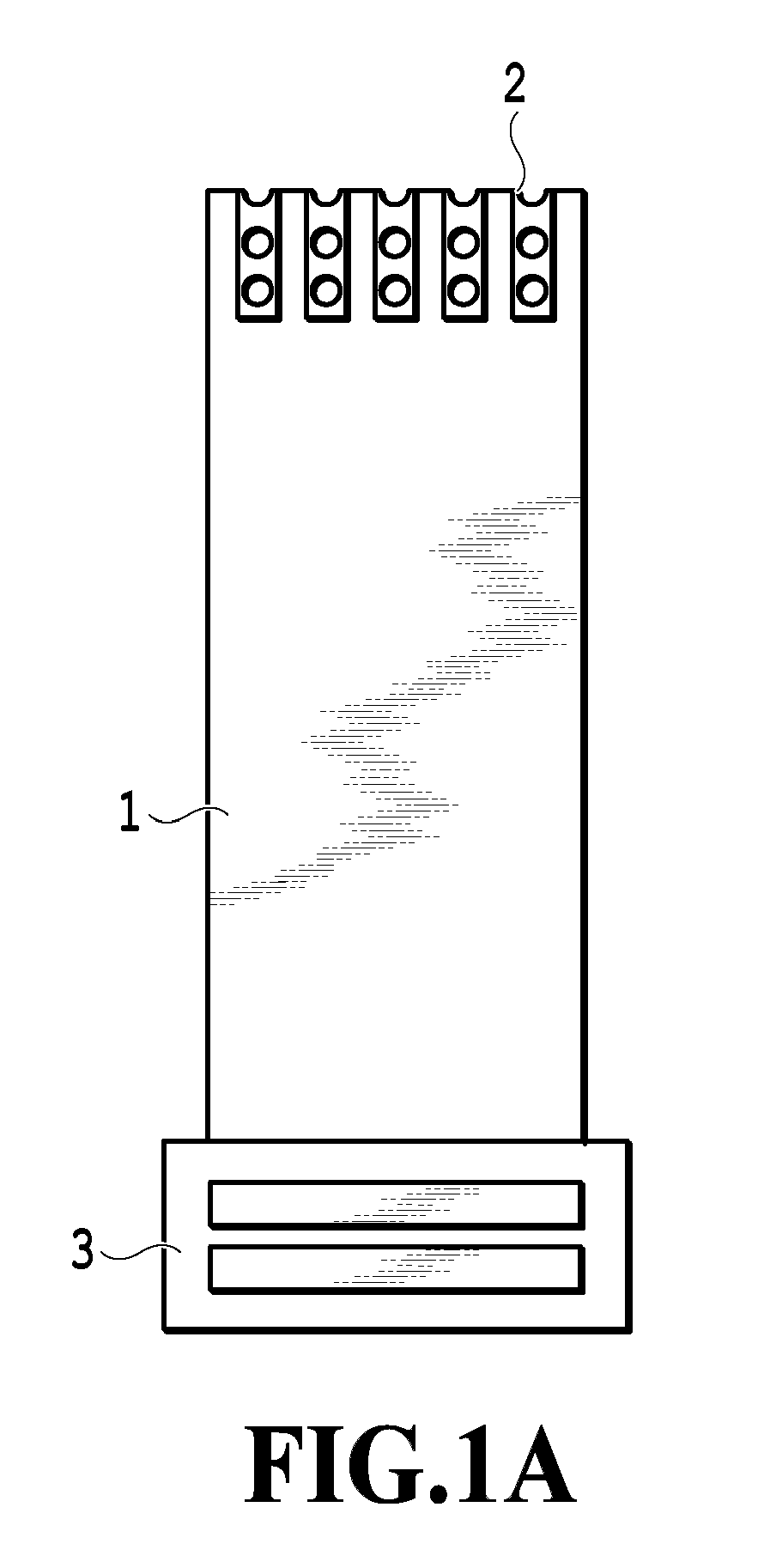
[0052]FIGS. 4A and 4B are views illustrating a structure of an unfolded state of a flexible substrate in Embodiment 1 of the present invention. FIG. 4A is a view of a side of the flexible substrate on which solder joint surfaces and pins of a connector are seen, whereas FIG. 4B is a view of the side opposite to FIG. 4A. A flexible substrate 40 includes a connector 43 at one end thereof, the connector 43 equipped with multiple pins for connection. A first body 42 and a second body of the flexible substrate are connected with the connector 43. The second body includes three side portions (41a, 41b, 41c) and is in a band-like form in an approximately squared-U or U shape, as will be described later. Both the first body 42 and the second body 41 are provided with a conductor foil formed using a film-form insulator as a base, as in the flexible substrates illustrated in FIGS. 1A and 2A. Although not illustrated in FIGS. 4A and 4B, the first body 42 and the second body 41 are joined to ea...
embodiment 2
[0066]FIGS. 7A and 7B are views illustrating structures of flexible substrates in Embodiment 2 of the present invention, and each present an unfolded state before folding-up. FIGS. 7A and 7B illustrate two different modification examples. The basic structure is the same as the structure of the flexible substrate in Embodiment 1 illustrated in FIGS. 4A and 4B, and only different points from those in Embodiment 1 are explained herein. A flexible substrate 70 in FIG. 7A illustrates a first modification example, and is different from the structure in Embodiment 1 only in the structure of a second body (71a and 71b). In Embodiment 1 illustrated in FIGS. 4A and 4B, the second body includes the two side portions 41a, 41b extending in parallel to the longitudinal direction of the whole flexible substrate, and the transverse side portion 41, and is formed in the closed band-like form to surround the periphery of the first body 42.
[0067]In Modification Example 1 in FIG. 7A, the second body (7...
embodiment 3
[0071]In the present embodiment, illustrated is a structural example in which the work in soldering the flexible substrates in aforementioned Embodiments of the present invention to optical transmission modules or the like is facilitated to be more efficiently carried out. In the flexible substrate in the present invention, the structure in which the second body is unsharply folded in the longitudinal direction of the whole flexible substrate significantly reduces the peel stress due to the stiffness of the folded portion in the soldering process of the two bodies. However, the soldering step of the second body involving reheating needs cautions on the work for minimizing the aforementioned stress. In the present embodiment, illustrated is the structural example that reduces the stress which is applied during the work in the soldering process due to variations in skill among workers.
[0072]FIGS. 8A and 8B are views for explaining a structure of a flexible substrate in Embodiment 3 of...
PUM
 Abstract
Description
Claims
Application Information
 - R&D
- Intellectual Property
- Life Sciences
- Materials
- Tech Scout
- Unparalleled Data Quality
- Higher Quality Content
- 60% Fewer Hallucinations
Browse by: Latest US Patents, China's latest patents, Technical Efficacy Thesaurus, Application Domain, Technology Topic, Popular Technical Reports.
© 2025 PatSnap. All rights reserved.Legal|Privacy policy|Modern Slavery Act Transparency Statement|Sitemap|About US| Contact US: help@patsnap.com


