Clamping device for reducing venous blood flow

a technology clamping device, which is applied in the field of venous blood flow reduction clamping device, can solve the problems of unsanitary repeated use of traditional tourniquets, increased risk of communication of disease, and fluid may splatter on the body, so as to reduce the venous blood flow in the limb

Active Publication Date: 2018-08-07
TOURNICARE PTY LTD
View PDF10 Cites 2 Cited by
  • Summary
  • Abstract
  • Description
  • Claims
  • Application Information

AI Technical Summary

Benefits of technology

[0009]wherein the first and second inner profiles are arranged to press against veins in the limb when the device is in the clamped position and thereby reduce venous blood flow in the limb.
[0016]The first and second rigid parts may be sized and shaped so that, when the device is positioned on the arm and is in the clamped position, the device cannot be easily removed from the upper arm. The first and second rigid parts may be sized and shaped so that, when the device is in the unclamped position, the device can be easily put on the upper arm or removed from the upper arm.
[0028]a bridge coupling the first and second jaws together in a manner that allows relative movement of the first and second jaws between an open position, in which the device can be positioned about at least a portion of the limb, and a clamped position, in which the inner faces of the first and second jaws are pressed against the opposite sides of the limb such that venous blood flow is reduced in at least superficial veins distal of the portion of the limb.

Problems solved by technology

In some circumstances, blood or other bodily fluids may splatter onto the tourniquet and the tourniquet may pick up and harbour bacteria from the skin during repeated use.
Such repeated use of traditional tourniquets is therefore unhygienic and involves a risk of communication of disease.
Additionally, traditional tourniquets require the use of two hands to apply them, which can be awkward if the medical practitioner is therefore unable to perform another desired function simultaneously.
Some traditional tourniquets may, when released, experience a somewhat violent and sudden release, which can be irksome for the patient or medical practitioner releasing the tourniquet.
Further, some traditional tourniquets may tend to pinch the skin of the patient when applying compression to the limb, causing pain and discomfort.
Further, traditional tourniquets do not allow a medical practitioner to tell how much pressure is being applied.
If the tourniquet is applied too tightly or too loosely, it can negatively affect the distension of veins in the limb around which the tourniquet is applied, which in turn can negatively affect patient outcomes.

Method used


Image

  • Clamping device for reducing venous blood flow
  • Clamping device for reducing venous blood flow
  • Clamping device for reducing venous blood flow

Examples


Embodiment Construction

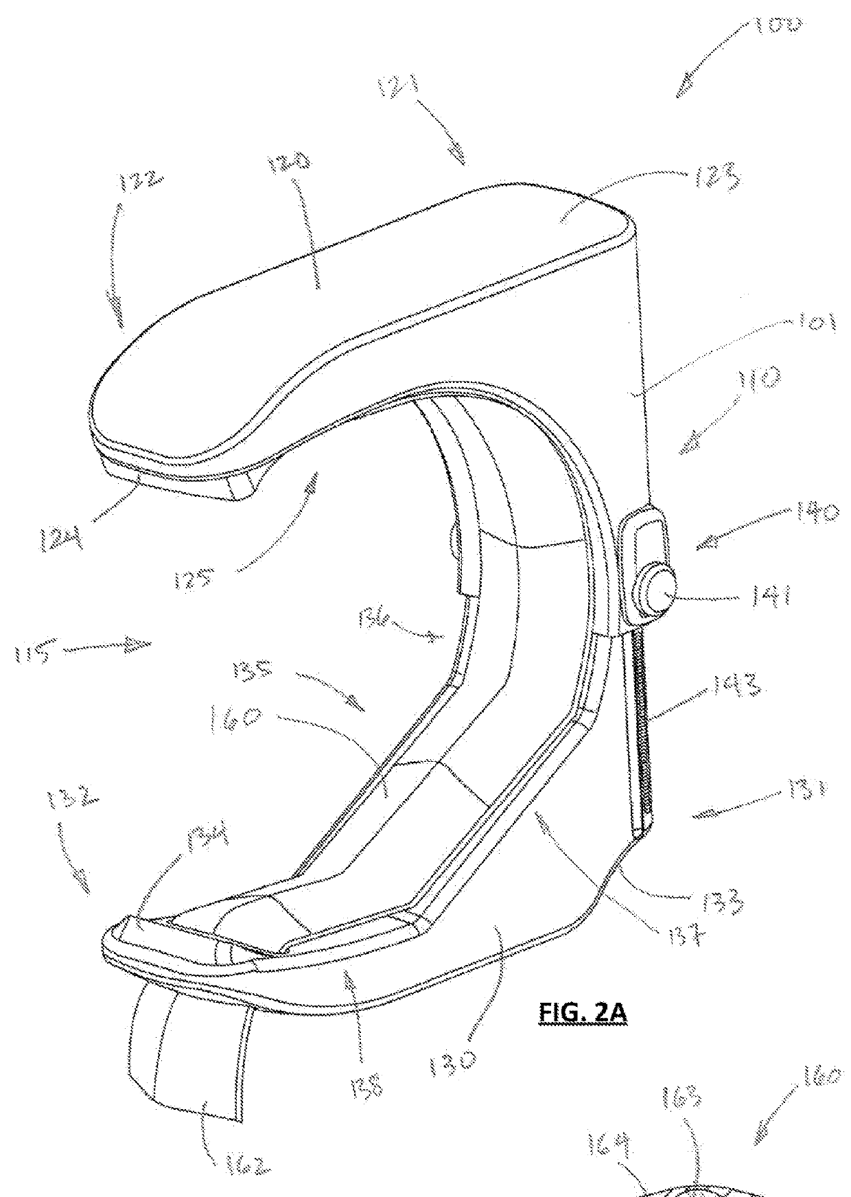
[0092]Described embodiments generally relate to clamping devices for reducing venous blood flow. In particular, embodiments relate to clamping devices with opposed parts (jaws) that are movable between a clamped position and an unclamped position about a limb.

[0093]In contrast to a circumferential tourniquet design that envelopes the upper arm or other limb in total, the described and claimed clamping devices are closer to a clamp / brace-style design, optionally with pressure points where needed to compress the main veins in the upper arm or other limb. This clamp-style device design may advantageously reduce patient discomfort, injury risk and improve efficiency in application of compression as part of the venepuncture procedure. Additionally, the open U-shape of described embodiments allows a disposable liner to be easily applied to the device and removed for disposal to provide improved hygiene.

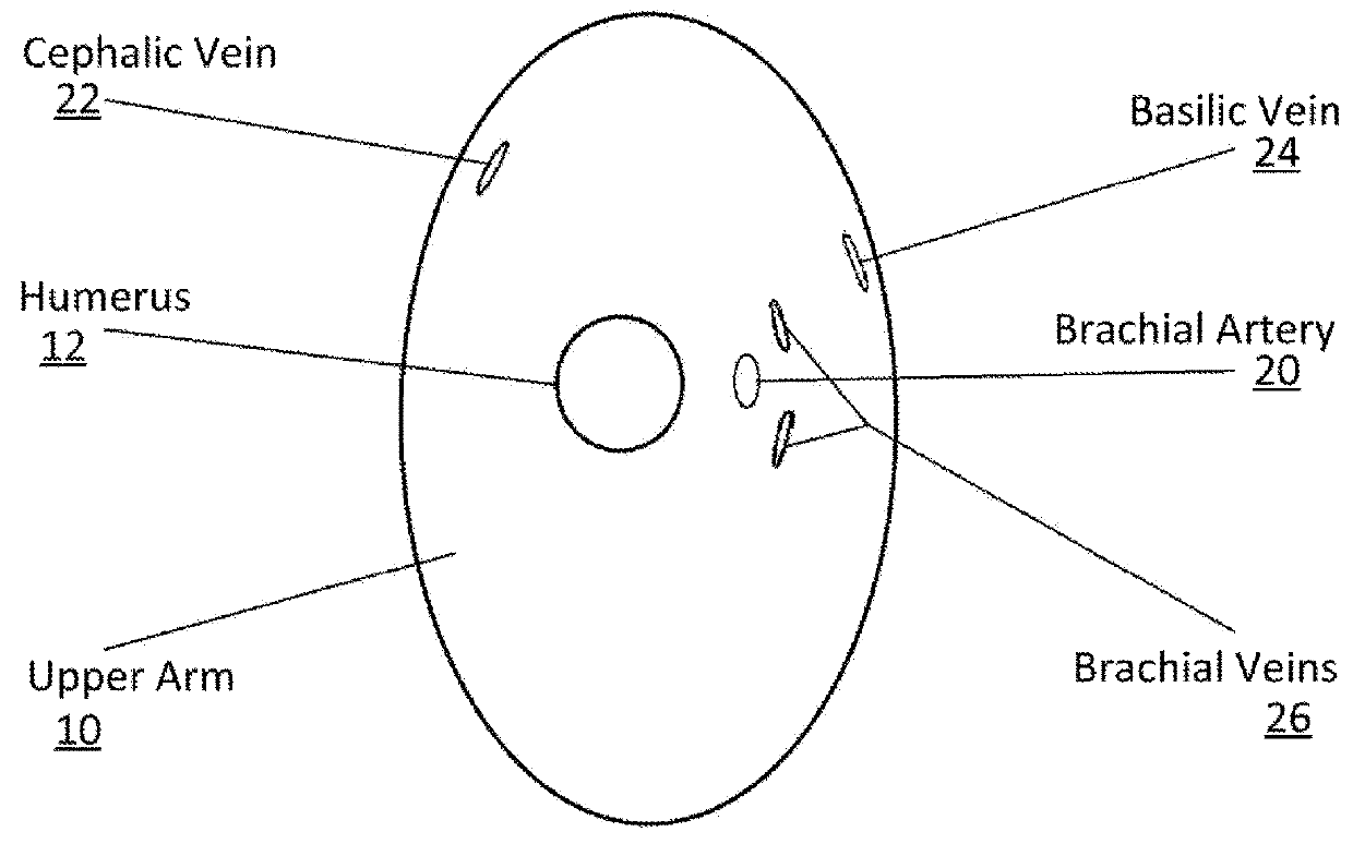
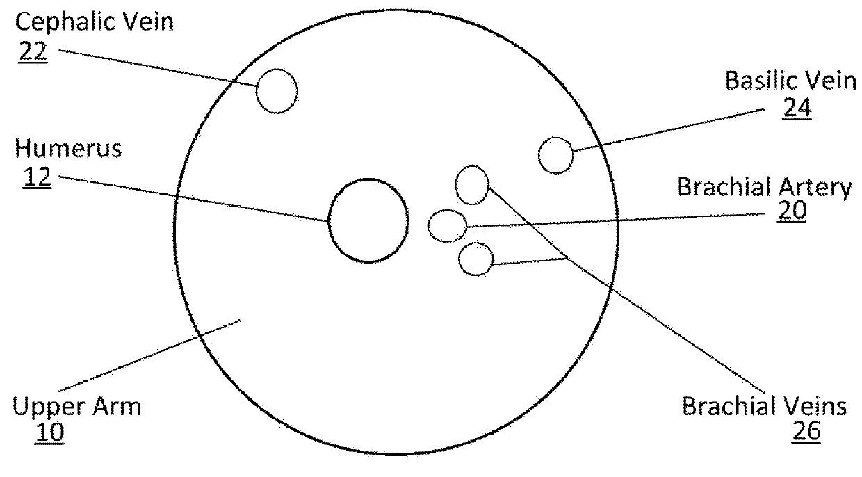
[0094]Referring firstly to FIGS. 1A and 1B, certain parts of the anatomy of the upper h...


PUM


Abstract

Some embodiments relate to a device for reducing venous blood flow in a human limb. The device of some embodiments comprises: a first rigid part having a first non-linear inner profile; a second rigid part having a second inner profile generally facing the first inner profile; and a coupling portion that couples the first and second parts together while allowing relative movement of the first and second parts between a clamped position and an unclamped position. The first and second inner profiles are arranged to press against veins in the limb when the device is in the clamped position and thereby reduce venous blood flow in the limb.

Description

TECHNICAL FIELD[0001]Described embodiments generally relate to clamping devices for reducing venous blood flow. In particular, embodiments relate to clamping devices with opposed parts that are movable between a clamped position and an unclamped position about a limb.BACKGROUND ART[0002]Tourniquets have been used traditionally for many years when performing venepuncture. Such tourniquets generally consist of a flexible band to encircle the arm or lower limb and compress the arm or lower limb around the circumference of that limb. It has been common practice to use such tourniquets repeatedly for multiple patients. In some circumstances, blood or other bodily fluids may splatter onto the tourniquet and the tourniquet may pick up and harbour bacteria from the skin during repeated use. Such repeated use of traditional tourniquets is therefore unhygienic and involves a risk of communication of disease.[0003]Additionally, traditional tourniquets require the use of two hands to apply them...

Claims


Application Information

Patent Timeline
Patent Type & Authority Patents(United States)
IPC IPC(8): A61B17/00A61B17/135A61B17/132A61B17/12
CPCA61B17/132A61B17/1355A61B17/135A61B2017/12004A61B2090/065
Inventor VAN SPARRENTAK, NIELSWHITE, ROHAN
Owner TOURNICARE PTY LTD
Why Eureka
Try Eureka