Plate-shaped workpiece transfer apparatus and processing apparatus

a technology of transfer apparatus and workpiece, which is applied in the direction of manipulators, electrical apparatus, gripping heads, etc., can solve the problems of reducing the workpiece transfer apparatus and chuck table damage, and achieve the effect of suppressing the damage to the apparatus

Active Publication Date: 2018-08-07
DISCO CORP
View PDF9 Cites 4 Cited by
  • Summary
  • Abstract
  • Description
  • Claims
  • Application Information

AI Technical Summary

Benefits of technology

[0005]It is therefore an object of the present invention to provide a plate-shaped workpiece transfer apparatus and a processing apparatus which can suppress possible damage to the apparatus without the need for increasing the number of man-hours required for adjustment of the position of each part of the apparatus.
[0010]According to the plate-shaped workpiece transfer apparatus and the processing apparatus of the present invention, possible damage to the apparatus can be suppressed without the need for increasing the number of man-hours required for adjustment of the position of each part.

Problems solved by technology

However, in the transfer mechanism described in Japanese Patent Laid-open No. 2007-258450 or 2012-064872, there is a problem such that the number of man-hours required for adjustment of the position of each part of the mechanism is increased to prevent the above possibility that the holding portion for engaging the outer edge of the plate-shaped workpiece may collide with the holding surface of the chuck table to cause damage to the chuck table.

Method used


Image

  • Plate-shaped workpiece transfer apparatus and processing apparatus
  • Plate-shaped workpiece transfer apparatus and processing apparatus
  • Plate-shaped workpiece transfer apparatus and processing apparatus

Examples


first preferred embodiment

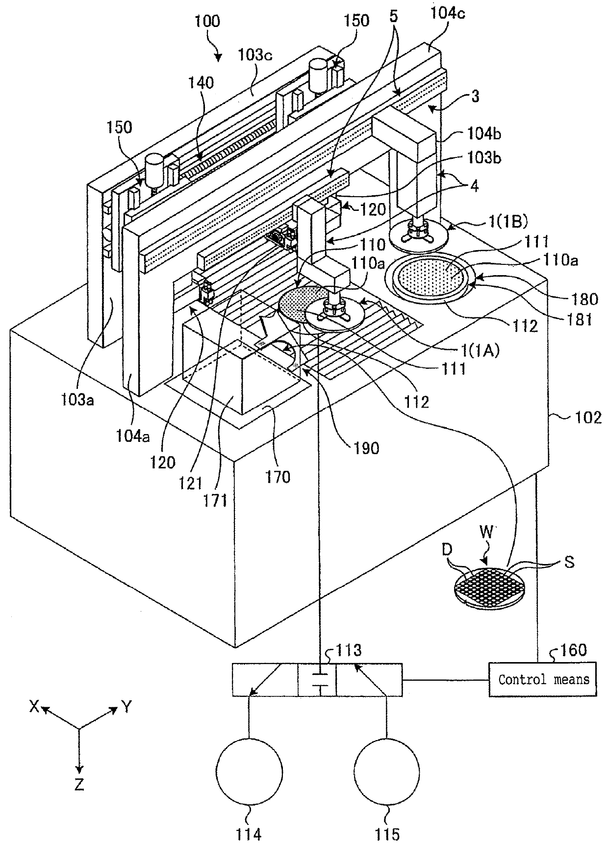
[0036]A plate-shaped workpiece transfer apparatus and a processing apparatus according to a first preferred embodiment of the present invention will now be described with reference to the drawings. Referring to FIG. 1, there is depicted a cutting apparatus 100 as a processing apparatus including a plate-shaped workpiece transfer apparatus 1 according to the first preferred embodiment. The cutting apparatus 100 is an apparatus for cutting (processing) a plate-shaped workpiece W.

[0037]In the first preferred embodiment, the workpiece W is a disk-shaped semiconductor wafer or optical device wafer formed of silicon, sapphire, gallium arsenide, for example, as a base material. The workpiece W has a front side on which a plurality of devices D are formed so as to be separated from each other by a plurality of crossing streets S. While the workpiece W in the first preferred embodiment is a semiconductor wafer or optical device wafer having a uniform thickness, the workpiece in the present i...

second preferred embodiment

[0073]A plate-shaped workpiece transfer apparatus and a processing apparatus according to a second preferred embodiment of the present invention will now be described with reference to the drawings. FIG. 15 is a sectional view of an essential part of the plate-shaped workpiece transfer apparatus according to the second preferred embodiment. FIG. 16 is a sectional view depicting a condition that each holding member depicted in FIG. 15 has been oscillated. In FIGS. 15 and 16, the same parts as those of the first preferred embodiment are denoted by the same reference symbols, and the description thereof will be omitted.

[0074]Referring to FIG. 15, there is depicted an essential part of a plate-shaped workpiece transfer apparatus 1-2 included in a cutting apparatus 100 (not depicted) as a processing apparatus according to the second preferred embodiment. As depicted in FIG. 15, a circular hole 31a-2 is formed at one end portion of each link 31. The small-diameter portion 11b of each hold...


PUM


Abstract

Apparatus transfers a plate-shaped workpiece to / from a holding surface of a chuck table. The apparatus includes a holding unit and a moving mechanism. The holding unit includes at least two holding members for holding the outer edge of the workpiece, a support plate for supporting the holding members so as to allow movement of the holding members toward or away from the outer edge of the workpiece, and a moving unit for moving the holding members. Each holding member includes a rod portion vertically movably extending downward through the support plate, an engaging portion formed on the outer circumference of the rod portion at the lower end thereof for engaging the outer edge of the workpiece, and a nozzle portion for discharging a fluid from the lower surface of the rod portion toward the holding surface to thereby float the workpiece from the holding surface.

Description

BACKGROUND OF THE INVENTIONField of the Invention[0001]The present invention relates to a plate-shaped workpiece transfer apparatus and a processing apparatus.Description of the Related Art[0002]Conventionally known is a processing apparatus for processing a plate-shaped workpiece such as a semiconductor wafer, packaged substrate, and glass substrate. For example, such a plate-shaped workpiece is thinned or divided into individual device chips by the processing apparatus. In general, the plate-shaped workpiece is transferred in the condition where it is held under suction by a vacuum pad or the like in the processing apparatus. However, there is a case that the adhesion of foreign matter to the front side of the plate-shaped workpiece is undesirable, that any unevenness is present on the front side of the plate-shaped workpiece, or that a circular recess is formed on the back side of the plate-shaped workpiece and an annular projection is accordingly formed so as to surround the cir...

Claims


Application Information

Patent Timeline
Patent Type & Authority Patents(United States)
IPC IPC(8): B25J15/06B25J15/00H01L21/687H01L21/683H01L21/67
CPCB25J15/0616B25J15/0014H01L21/68721H01L21/6838H01L21/67092H01L21/67742H01L21/683H01L21/67751H01L21/68707H01L21/68728B25J15/10H01L21/67739H01L21/67017H01L21/68
Inventor TERADA, KAZUKI
Owner DISCO CORP
Why Eureka
Try Eureka