Capacitive sensor having bending portion and flat portion

a capacitive sensor and bending portion technology, applied in the field of capacitive sensors, can solve the problems of affecting the function of the capacitive sensor sensor, the resistance of the bridge wiring member may change accordingly, and so as to reduce the possibility of the sensor function becoming defective and the damage in the bridge structure.

Active Publication Date: 2020-02-18
ALPS ALPINE CO LTD
View PDF27 Cites 3 Cited by
  • Summary
  • Abstract
  • Description
  • Claims
  • Application Information

AI Technical Summary

Benefits of technology

[0007]The present invention has been made to address the above-described existing issues, and provides a capacitive sensor that is bendable and in which damage in the bridge structure can be suppressed and the possibility of the sensor function becoming defective can be reduced.

Problems solved by technology

Then, damage, such as a crack, may occur in a bridge wiring member, and the resistance of the bridge wiring member may change accordingly.
When the resistance of the bridge wiring member changes, the sensor function of the capacitive sensor may be affected.

Method used


Image

  • Capacitive sensor having bending portion and flat portion
  • Capacitive sensor having bending portion and flat portion
  • Capacitive sensor having bending portion and flat portion

Examples


Embodiment Construction

[0034]Hereinafter, an embodiment of the present invention will be described with reference to the drawings. Note that, in the drawings, similar constituent elements are assigned the same reference numerals, and detailed descriptions thereof will be omitted as appropriate.

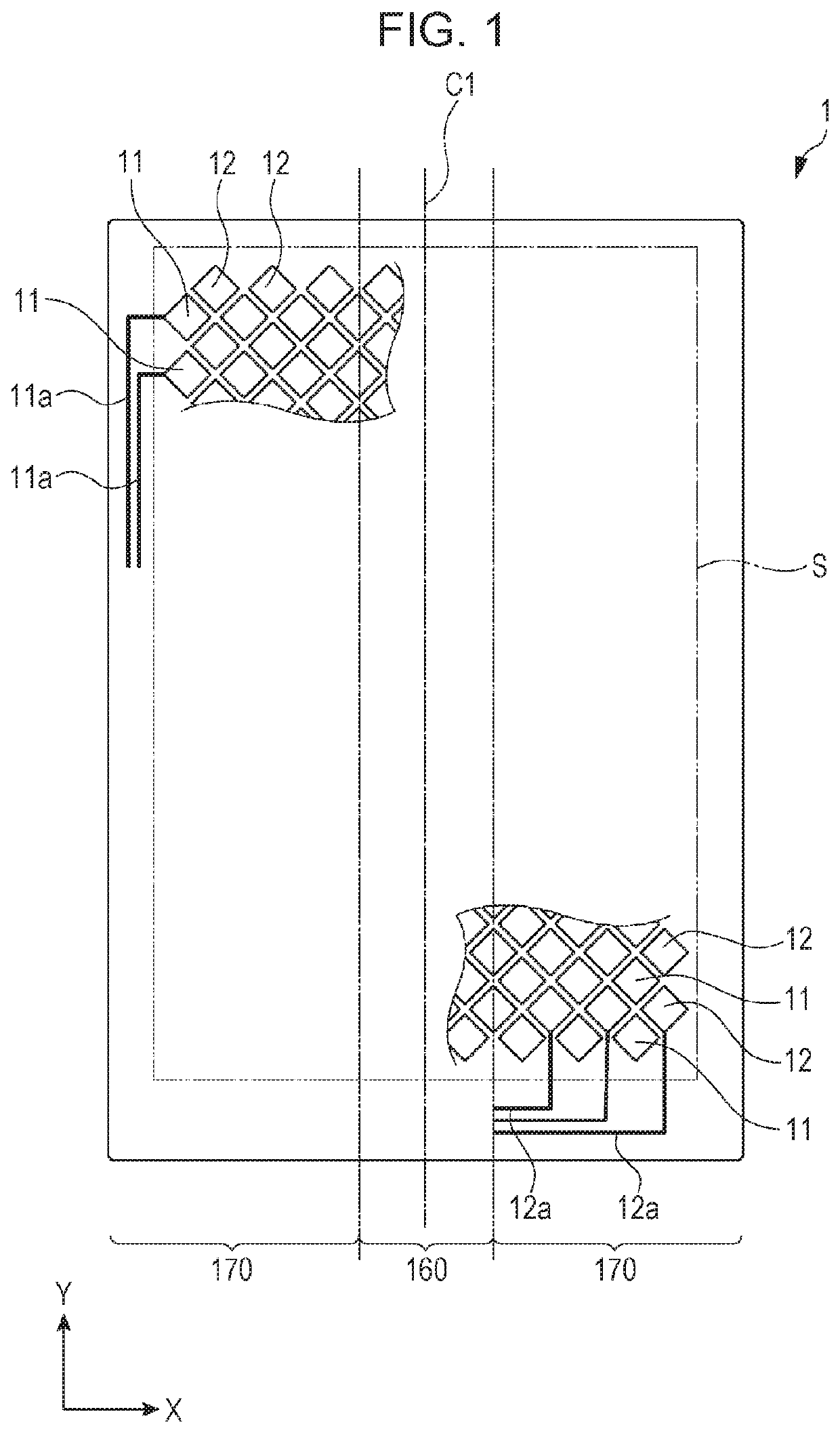
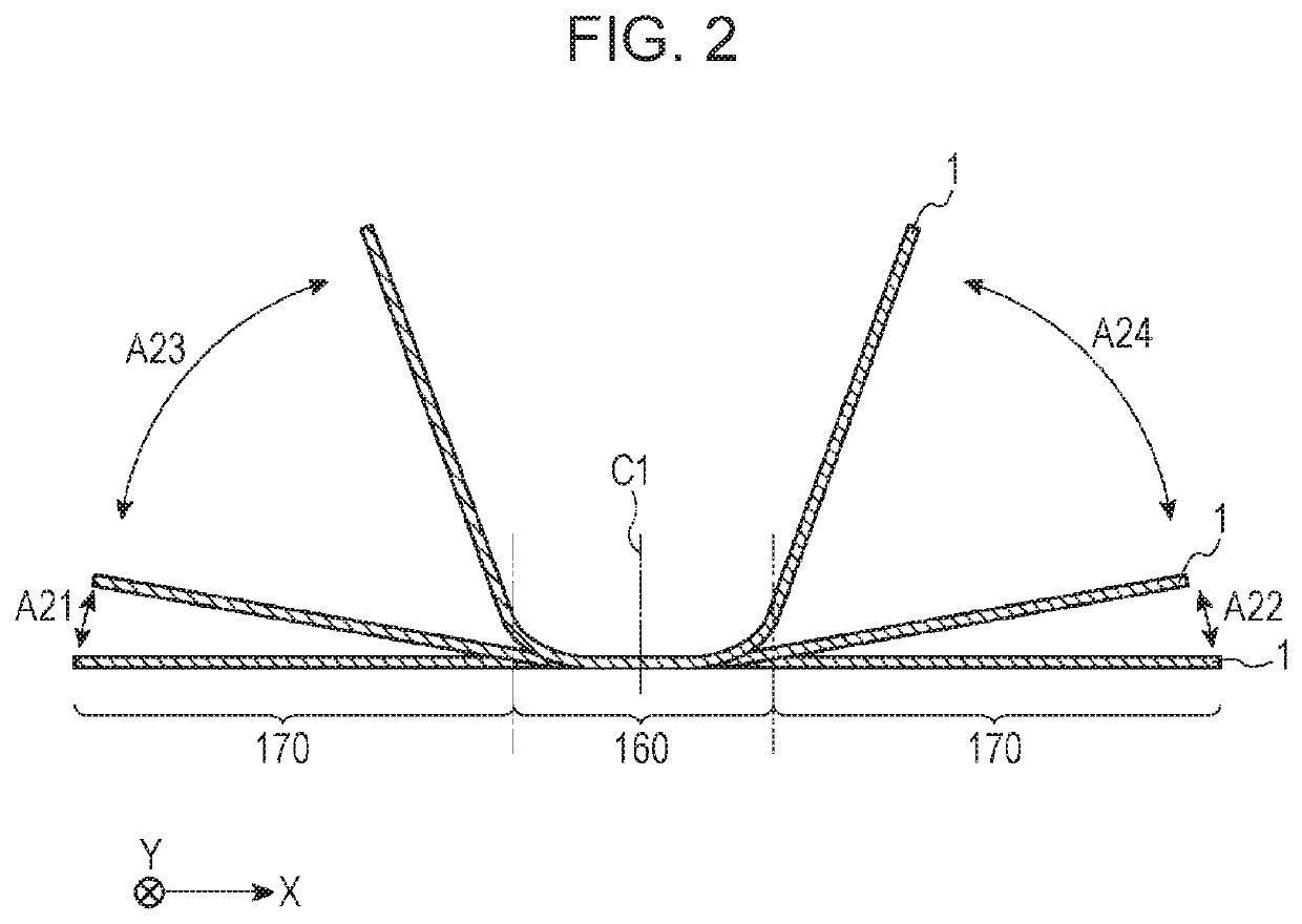
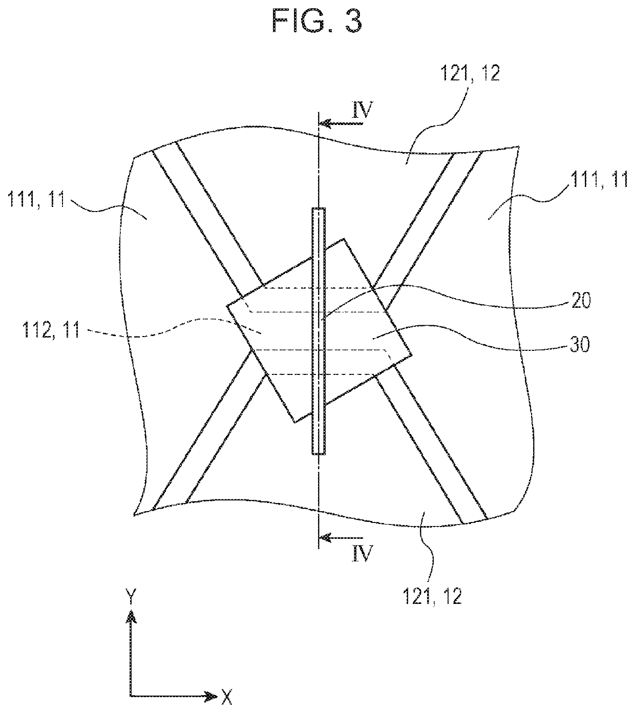
[0035]FIG. 1 is a schematic plan view illustrating a capacitive sensor according to the present embodiment. FIG. 2 is a schematic plan view illustrating a state where the capacitive sensor according to the present embodiment is bent. FIG. 3 is a schematic enlarged view illustrating a bridge wiring member in a bending portion. FIG. 4 is a schematic cross-sectional view taken along line IV-IV illustrated in FIG. 3. FIG. 5 is a schematic enlarged view illustrating a bridge wiring member in a flat portion. FIG. 6 is a schematic cross-sectional view taken along line VI-VI illustrated in FIG. 5.

[0036]The terms “transparent” and “light transparency” used herein indicate a state where the visible-light transmittance is 50% ...


PUM

PropertyMeasurementUnit
visible-light transmittanceaaaaaaaaaa
hazeaaaaaaaaaa

Abstract

A capacitive sensor having a bending portion and a flat portion and bendable in the bending portion includes a plurality of first transparent electrodes, a plurality of second transparent electrodes, a coupling member, and a bridge wiring member. The first transparent electrodes are arranged in a first direction. The second transparent electrodes are arranged in a second direction crossing the first direction. The coupling member is provided integrally with either the first transparent electrodes or the second transparent electrodes. The bridge wiring member is provided separately from the first transparent electrodes or the second transparent electrodes, to which the coupling member is not provided, in a portion where the bridge wiring member crosses the coupling member. A direction in which the coupling member extends in the bending portion is different from a direction in which the coupling member extends in the flat portion.

Description

CLAIM OF PRIORITY[0001]This application is a Continuation of International Application No. PCT / JP2016 / 086535 filed on Dec. 8, 2016, which claims benefit of Japanese Patent Application No. 2015-242043 filed on Dec. 11, 2015. The entire contents of each application noted above are hereby incorporated by reference.BACKGROUND OF THE INVENTION1. Field of the Invention[0002]The present invention relates to a capacitive sensor and relates specifically to a capacitive sensor that has a bridge structure (electrode-crossing structure) and that is bendable.2. Description of the Related Art[0003]A typical capacitive sensor includes a plurality of transparent electrodes having light transparency. In such a capacitive sensor, which has a bridge structure, a plurality of first transparent electrodes are coupled to each other in a first direction via bridge wires, and a plurality of second transparent electrodes are coupled to each other in a second direction via coupling members. The plurality of ...

Claims


Application Information

Patent Timeline
Patent Type & Authority Patents(United States)
IPC IPC(8): G06F3/044G01B7/16
CPCG06F3/044G01B7/22G06F2203/04111G06F2203/04102G06F3/04164G06F3/0443G06F3/0446B60W40/08
Inventor KOIKE, YUSUKEKOBAYASHI, KIYOSHITAKAHASHI, HIDEAKI
Owner ALPS ALPINE CO LTD
Why Eureka
Try Eureka