
Transfer substrate for forming metal wiring line and method for forming metal wiring line by means of said transfer substrate

a transfer substrate and metal wiring technology, applied in the direction of soldering equipment, manufacturing tools, liquid/solution decomposition chemical coating, etc., can solve the problem that the formation technique of metal plating cannot adequately deal with the miniaturization of metal, and achieve the effect of reducing load, stably transferring metal wiring, and suppressing damage to semiconductor chips or the like on the transfer targ

Active Publication Date: 2014-09-18
TANAKA PRECIOUS METAL IND
View PDF0 Cites 3 Cited by
  • Summary
  • Abstract
  • Description
  • Claims
  • Application Information

AI Technical Summary

Benefits of technology

The present invention provides a transfer substrate that can transfer metal wiring materials even at a low heating temperature, reducing damage to semiconductor chips during transfer. Additionally, the invention allows for the formation of a metal layer at a lower site of a bump without the need for metallization treatment of the transfer target, reducing the load placed on the transfer target.

Problems solved by technology

However, there is a concern that the bump formation with a plating technique cannot sufficiently deal with miniaturization of metal wiring that is likely to make more progress in the future.

Method used


Image

  • Transfer substrate for forming metal wiring line and method for forming metal wiring line by means of said transfer substrate
  • Transfer substrate for forming metal wiring line and method for forming metal wiring line by means of said transfer substrate

Examples


Embodiment Construction

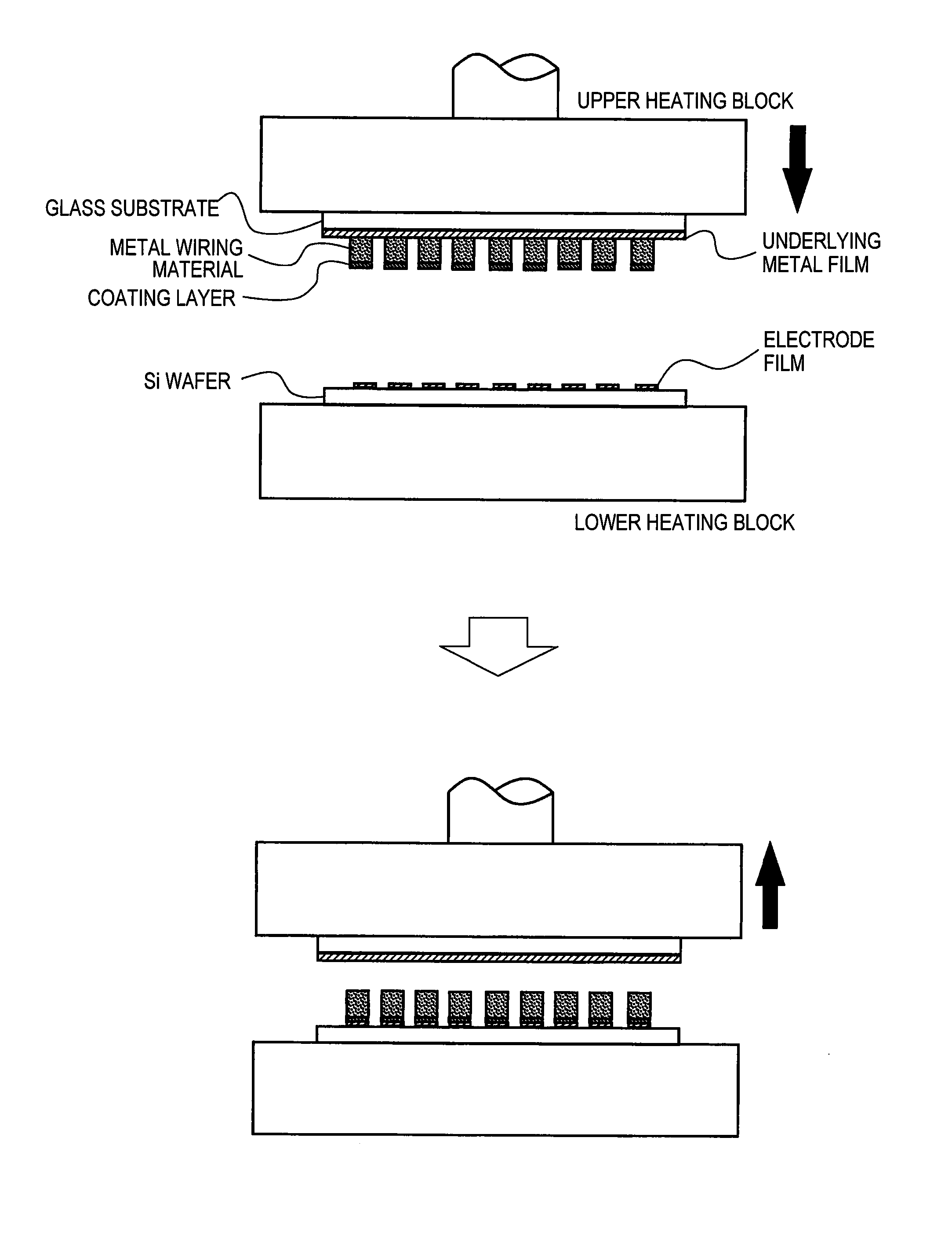
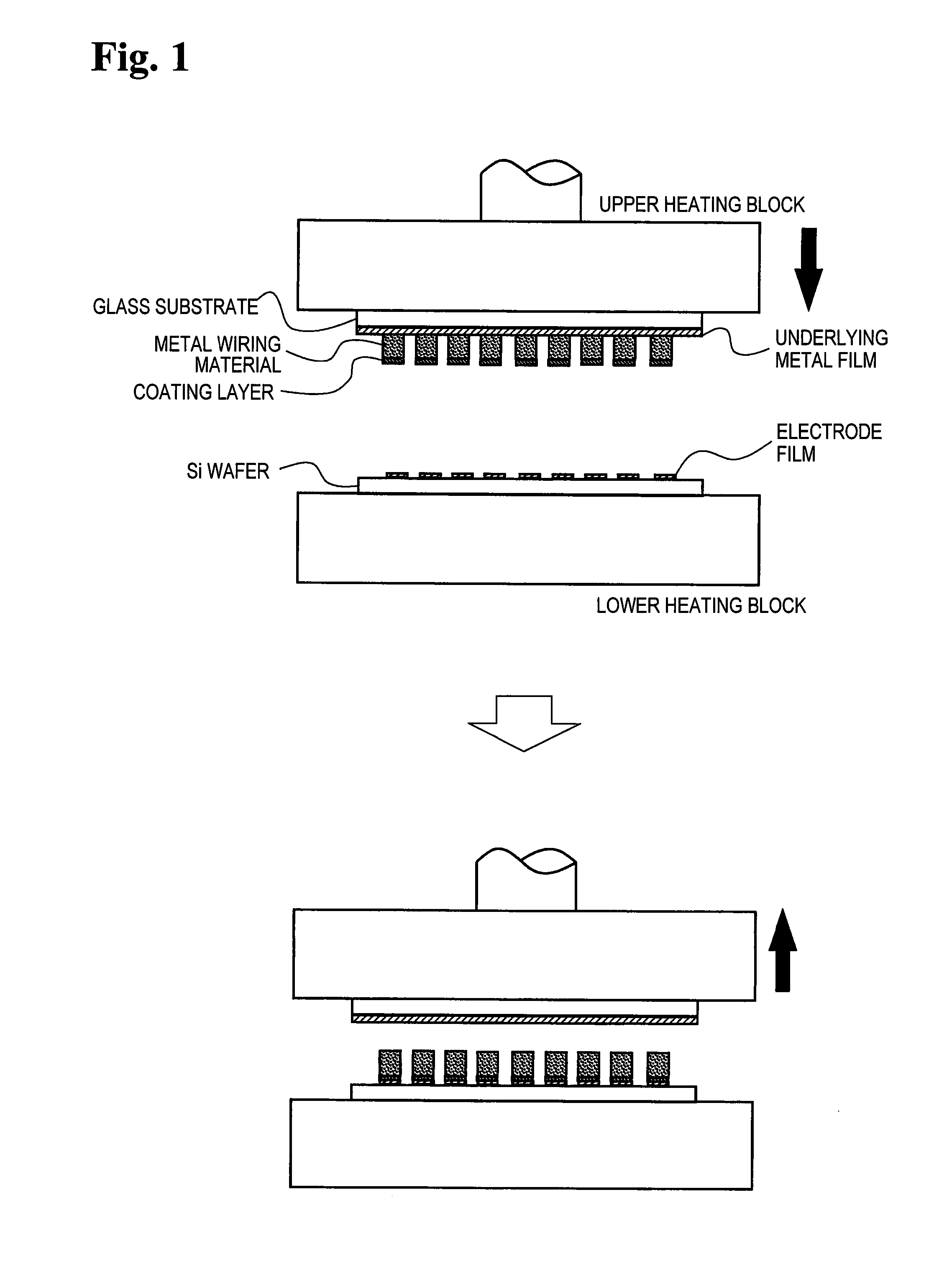
[0039]First Embodiment: a transfer substrate was prepared with a glass substrate, and with this being used, metal wiring formation on a Si wafer was performed.

(Production of the Transfer Substrate)

[0040]First, Pt was film-formed with sputtering as an underlying metal film on a glass substrate (diameter size 100 mm, 4 inches, average thickness 500 μm). In the Pt film formation, after the glass substrate was subject to cleaning with reverse sputtering (Ar pressure 2.8×10⁻¹ Pa, RF output 250 W, sputtering time 60 seconds), the film formation was performed with use of a Pt target under conditions of Ar pressure 7.0×10⁻¹ Pa, DC output 500 W and sputtering time 115 seconds, and thus a Pt film having a thickness of 20 nm was formed.

[0041]Next, a metal wiring material was formed on a glass substrate with use of a metal paste made of Au powder. The metal paste used here was adjusted with a mixture of gold powder (average particle size: 0.3 μm) of a purity of 99.95 wt % produced with a wet re...


PUM

PropertyMeasurementUnit
particle sizeaaaaaaaaaa
thicknessaaaaaaaaaa
thicknessaaaaaaaaaa

Abstract

A transfer substrate for transferring a metal wiring material to a transfer target including a substrate, at least one metal wiring material formed on the substrate, at least one coating layer formed on a surface of the metal wiring material, and an underlying metal film formed between the substrate and the metal wiring material, in which the metal wiring material is a compact formed by sintering metal powder such as gold powder having a purity of 99.9 wt % or more and an average particle size of 0.01 μm to 1.0 μm, and the coating layer is a predetermined metal such as gold or an alloy having a different composition from that of the metal wiring material and has a total thickness of 1 μm or less, and the metal underlying film is made of a predetermined metal such as gold or an alloy. The transfer substrate can lower heating temperature on the transfer target side.

Description

BACKGROUND OF THE INVENTION[0001]1. Field of the Invention[0002]The present invention relates to a transfer substrate for forming a metal wiring on a transfer target such as a semiconductor wafer, a compound wafer and a MEMS wafer, and relates to a metal wiring method using the same.[0003]2. Description of the Related Art[0004]With increasing packaging density of electronic components such as a semiconductor chip, their implementation method has changed from a conventional wire bonding method to a wireless implementation method such as a flip-chip bonding method in which a semiconductor chip is directly mounted on a circuit board, which has become a mainstream. A manufacturing process of electronic components using this implementation method is a process in which a bump is formed on a terminal electrode on a semiconductor chip of a device wafer or on an external electrode for connecting to a semiconductor chip, thus metal wiring being made up, and then this is face-down bonded onto ...

Claims


Application Information

Patent Timeline
Patent Type & Authority Applications(United States)
IPC IPC(8): H01L21/48H01L21/71
CPCH01L21/71H01L21/4814H01L24/11H01L24/13H01L24/94H01L2224/11505H01L2224/13082H01L2224/13144H01L2224/13139H01L2224/11003H01L2224/111H01L2224/11334H01L2224/13166H01L2224/13164H01L2224/13155H01L2224/13147H01L2224/1317H01L2224/13169H01L2224/13181H01L2224/13178H01L2224/13176H01L2224/13173H01L2224/13184H01L2224/13171H01L2224/94H01L2924/1461C25D7/00H01L2224/11H01L2924/00014H01L2924/00H01L2924/15788H01L24/05H01L2224/0401H01L2224/05082H01L2224/05166H01L2224/05169H01L2224/05644H01L2224/03334B23K35/3006B23K35/3013B22F7/08B23K35/322B23K35/0244H01L24/03H01L2224/03003H01L2224/031H01L2224/0312H01L2224/0508H01L2224/05083H01L2224/05139H01L2224/05144H01L2224/05639H01L2224/05647H01L2224/05655H01L2224/05664H01L2224/05666H01L2224/05669H01L2224/0567H01L2224/05671H01L2224/05673H01L2224/05676H01L2224/05678H01L2224/05681H01L2224/05684H01L2224/13083H01L2924/01006H01L2924/01024H01L2924/01029H01L2924/01033H01L2924/0104H01L2924/01044H01L2924/01045H01L2924/01047H01L2924/01073H01L2924/01074H01L2924/01077H01L2924/01078H01L2924/01079H01L2224/1112H01L2924/181B23K35/007B23K35/025B23K2035/008B32B15/018C22C5/02C22C5/04C23C18/165B23K2101/40Y10T428/12056H01L2924/01046H01L2924/00012
Inventor OGASHIWA, TOSHINORIKURITA, MASAAKINISHIMORI, TAKASHIKANEHIRA, YUKIO
Owner TANAKA PRECIOUS METAL IND
Learn More