Cable-traversing trolley adapted for use with impact braking

a trolley and cable technology, applied in the direction of brake systems, mechanical devices, transportation and packaging, etc., can solve the problems of trolley damage, much greater danger and risk to participants, and damage to loads

Active Publication Date: 2018-08-14
TRUBLUE
View PDF55 Cites 7 Cited by
  • Summary
  • Abstract
  • Description
  • Claims
  • Application Information

AI Technical Summary

Benefits of technology

[0003]Growth in commercial, recreational zip lines have been significant in recent years, a trend that appears will continue for the foreseeable future. The growth of the industry has coincided with higher rider speeds, longer descents—and much greater danger and risk to participants. With demand for greater speed also comes a need for safely braking participants. In essence, demand has significantly outpaced the technology to ensure safety to riders.
[0010]A secondary brake, sometimes also referred to as an emergency arrest device (EAD) may also be provided (not shown). The EAD may take the form of a second brake or some other device to prevent injury to the rider due to impact with the lower anchor in case of a failure in the primary braking system shown.
[0012]Many existing zip line rider trolley designs employ a fixed handle that is attached to the trolley, in which a rider can hold onto grips to control his / her orientation during a descent. Such a handle / grip has two advantages: a.) it allows the rider to arrive at the terminal platform facing forwards (this decreases the odds of a riders head from impacting the cable during deceleration swing as may more likely occur when a rider is facing backward during breaking), and b.) the handle minimizes the possibilities of a riders being injured due to impact with braking components (for example, the likelihood that a hand or arm may be caught between trolley and brake mechanism is reduced because the hands are not free to move) during deceleration. However, use of a handle may result in significantly increased uplift forces on the trolley during deceleration, causing problems with brake interface (sometimes dramatically augmenting deceleration and rider swing), and damage to equipment, as is discussed in greater detail below.
[0013]FIG. 2 is two views of an existing rider trolley 200 used in zip line systems. In this design, the trolley has two sheaves 202 that rotate around pivot pins (not shown). The sheaves 202 are located between two opposing side plates 204 as shown. The side plates 204 are wide enough apart to accommodate the zip line 208 and to allow the rider trolley 200 to be placed on (installed) and removed from the zip line 208. An anchor point in the form of an aperture 206 is provided in each side plate 204 for attaching a cable connected to a rider or other payload to the trolley. When an anchor coupling, such as a carabiner, is passed through the anchor points 206 of both plates 204 of a rider trolley 200 installed on a zip line 102, the carabiner may also lock the rider trolley to the zip line 208 preventing the trolley from being removed or from falling off. Because the anchor points 206, when installed on a zip line, are equidistant from the two sheaves 202, when a sufficiently heavy payload is attached in this way, the sheaves 202 are substantially equally loaded against the zip line 102 so that both sheaves 202 easily roll along the zip line.Cable-traversing Trolley Adapted for Use with Impact Braking

Problems solved by technology

The growth of the industry has coincided with higher rider speeds, longer descents—and much greater danger and risk to participants.
When braking a suspended load that is traveling at medium to high velocity, the load has a strong tendency to swing upward or shift once braking force is applied to the trolley above, often resulting in unwanted consequences such as: injuries to riders, damages to loads, damage to trolleys, damage to braking components, increased braking force due to unintended consequences (such as trolleys lifting and creating drag on cables or other components), and / or lost efficiencies (such as loads not arriving at the intended location because of irregularities in braking requiring time to retrieve the load and place to the system back into service).
And while many devices and systems have been developed to provide braking force, mechanisms to constrain swing / shift have been absent.
Without a form of constraint during this deceleration, the rider continues forward and may impact the zip line above, becoming injured by the impact.
Additionally, the trolley may become displaced from the line (for example, the front sheave can lift off of the line), which can compound the problem and can lead to broken trolleys and zip line components.
This may occur for any number of reasons such as light riders relative to the brake resistance, poorly functioning rider trolley, and / or excessive headwinds.
However, use of a handle may result in significantly increased uplift forces on the trolley during deceleration, causing problems with brake interface (sometimes dramatically augmenting deceleration and rider swing), and damage to equipment, as is discussed in greater detail below.

Method used


Image

  • Cable-traversing trolley adapted for use with impact braking
  • Cable-traversing trolley adapted for use with impact braking
  • Cable-traversing trolley adapted for use with impact braking

Examples


second embodiment

[0055]FIG. 13 illustrates a rider trolley 1300 with a slotted side plate 1304 having a single load-bearing sheave 1302 above the zip-line 1308 and a counter-balancing, load-bearing sheave 1320 below the zip line. This embodiment has a slightly modified slot 1330 configuration and different side plate structural supports 1340, among other things as shown in the FIG.

[0056]FIG. 14 illustrates an embodiment of a rider trolley 1400 with a slotted side plate 1404 having a single load-bearing sheave above the zip-line 1408 and a counter-balancing, load-bearing sheave 1420 below the zip line, further provided with a T-handle 1450 for use by a rider. In the embodiment shown, the T-handle 1450 is attached adjacent to the lower load-bearing sheave 1420. The T-handle 1450 may be fixed to the trolley 1400 (as shown) or may be provided with a rotating pivot in order to allow some swing to the T-handle. In the embodiment shown, in addition to the anchor point 1406 a secondary anchor point 1407 may...

embodiment 1600

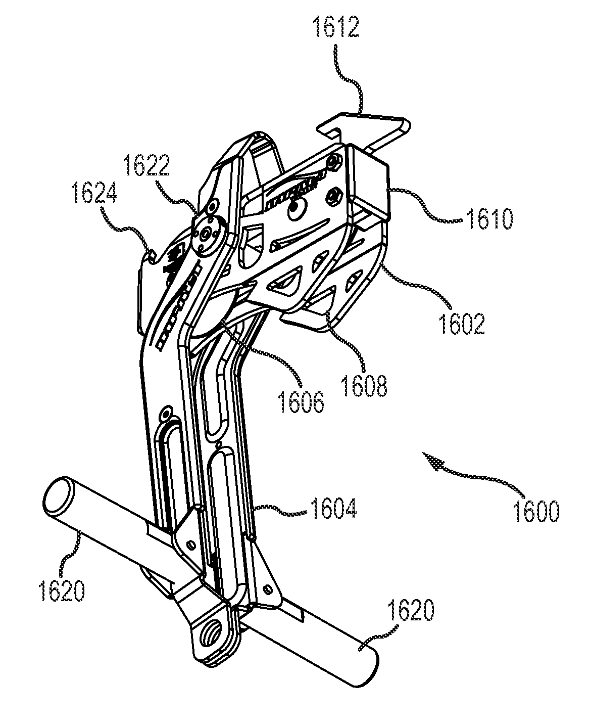
[0059]FIGS. 16A-D illustrates another embodiment of a rider trolley with a pivoting handle. In the embodiment 1600 shown, a trolley portion 1602 is pivotably attached to a handle and arm assembly 1604. The rider trolley 1602 is illustrated as having two sheaves 1606 in a trolley housing that includes side plates and anchor points 1608, as well as other components discussed in greater detail above. The housing may be made of any suitable material such as metal, carbon fiber or plastic. The housing may further be painted or anodized to improve the appearance or to provide protection against wear or the elements.

[0060]The housing is further provided with an impact surface 1610. A bumper or other shock absorbing device (not shown) may be attached to the impact surface 1610 to provide for a softer impact on the brake. The impact surface 1610 provides a greater surface area for engagement with the brake, which decreases the wear on both the brake and the trolley 1600. Furthermore, by plac...


PUM


Abstract

A trolley for traversing a zip line includes a first load-bearing sheave rotatably mounted to one or more side plates, and a second load-bearing sheave rotatably mounted to the one or more side plates and rearward of the first sheave. The trolley also includes an anchor point on the trolley for attaching a payload. When the trolley decelerates, forces acting on the payload create a downward load on the first sheave and the second sheave.

Description

RELATED APPLICATION[0001]This application claims the benefit of U.S. Provisional Application No. 61 / 968,205, filed Mar. 20, 2014, which application is hereby incorporated by reference.INTRODUCTION[0002]Zip lines, alternatively written as “ziplines” or “zip-lines,” refers to a form of entertainment in which a rider traverses a wire or other cable from one point to another. Typically, the traverse is powered by gravity, with the rider traveling from the high end of the zip line to the low end. Zip lines have become popular vacation activities and are becoming increasing common attractions at amusement parks, theme parks and vacation spots.[0003]Growth in commercial, recreational zip lines have been significant in recent years, a trend that appears will continue for the foreseeable future. The growth of the industry has coincided with higher rider speeds, longer descents—and much greater danger and risk to participants. With demand for greater speed also comes a need for safely braking...

Claims


Application Information

Patent Timeline
Patent Type & Authority Patents(United States)
IPC IPC(8): A63G21/22B60T11/04B61H9/02F16D63/00
CPCB60T11/046F16D63/008B61H9/02A63G21/22
Inventor MCGOWAN, JOHN
Owner TRUBLUE
Why Eureka
Try Eureka