
Roller lifter

a technology of rollers and rollers, applied in the direction of valve arrangements, fuel injection apparatuses, charge feed systems, etc., can solve the problem that the outer diameter of the cylindrical portion cannot be maintained in a proper dimensional accuracy

Inactive Publication Date: 2018-08-14
OTICS CORP
View PDF12 Cites 1 Cited by
  • Summary
  • Abstract
  • Description
  • Claims
  • Application Information

AI Technical Summary

Benefits of technology

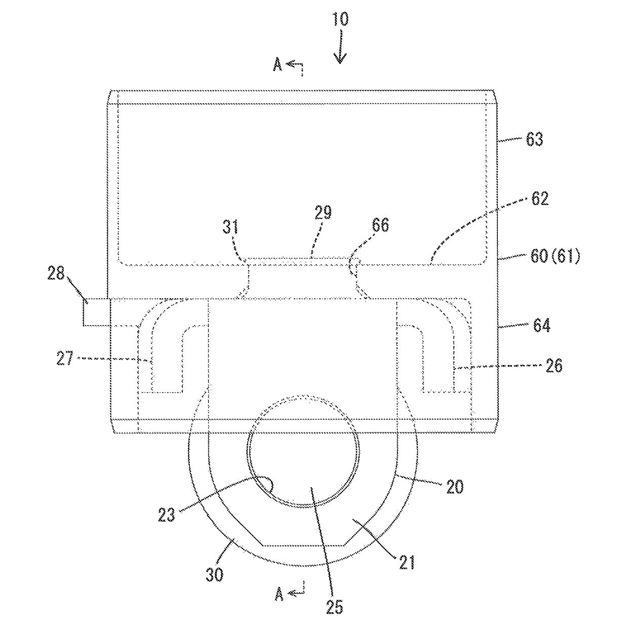
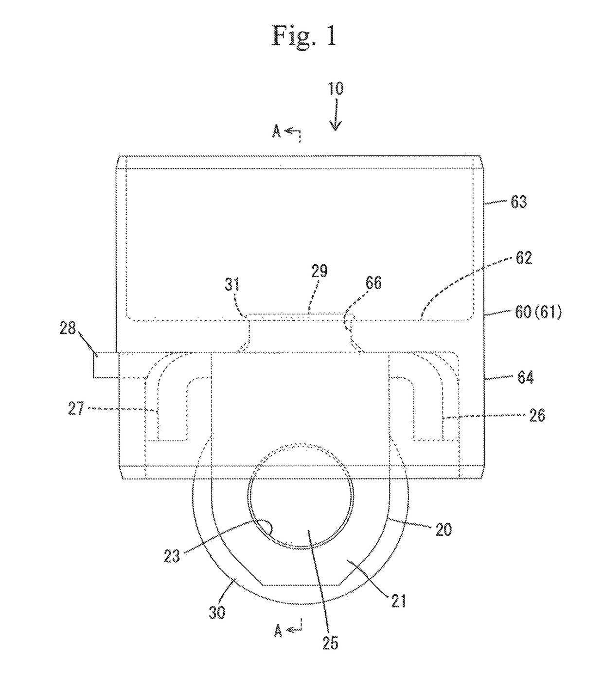
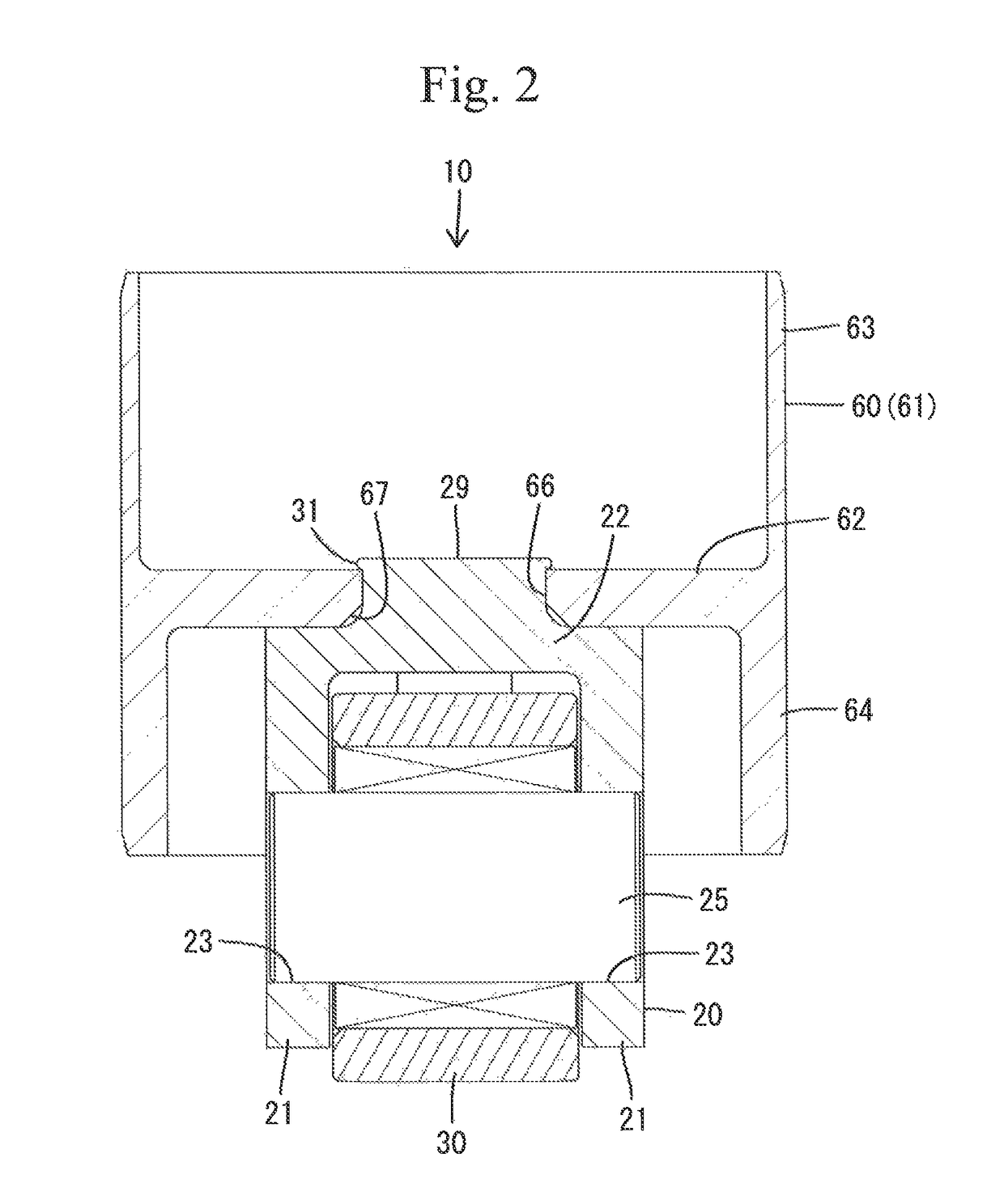
[0007]Even though the shaft is swaged to be fixed to the paired opposed portions, the outer diameter of the cylindrical portion can be maintained in a proper dimensional accuracy without influences of the swaging of the shaft reaching the cylindrical portion when the first member including the pair of opposed portions through which the ends of the shaft are inserted is coupled to the second member including the cylindrical portion.

Problems solved by technology

If the opposed portions are deformed, an outer peripheral wall of the cylindrical portion, which is integrally continuous from the opposed portions, would also be deformed with high possibility, with a result that an outer diameter of the cylindrical portion could not be maintained in a proper dimensional accuracy.

Method used


Image

  • Roller lifter
  • Roller lifter
  • Roller lifter

Examples


second embodiment

[0044]FIGS. 10 and 11 illustrate the present invention. The second embodiment differs from the first embodiment in that both ends of the shaft 25A are not swaged to be fixed to the outer surfaces of the opposed portions 21 and are slidably inserted into the bearing holes 23 of the opposed portions 21. However, the first and second members 20 and 60 have the same structures as those in the first embodiment respectively. Accordingly, the structures common to the first and second embodiments are labeled by the same reference symbols as those in the first embodiment and duplicate explanations will be eliminated in the following description.

[0045]The shaft 25A is rotatably supported via the bearing holes 23 by the opposed portions 21. Both ends of the shaft 25A are provided with retaining portions 19 which protrude so as to face surrounding portions 18 of the bearing holes 23 in the outer surfaces of the opposed portions 21 and are capable of being caught on the surrounding portions 18 o...


PUM


Abstract

An object is to provide a roller lifter which can maintain a proper dimensional accuracy of an outer diameter. A shaft (25) rotatably supporting a roller (30) is inserted through a pair of opposed portions (21) and swaged to be fixed. A cylindrical portion (61) is disposed to be fixed at a relative position to the opposed portions (21). Upon rotation of a cam (90), the cylindrical portion (61) is reciprocated via the roller (30). The roller lifter (10) includes a first member (20) in which the shaft (25) is swaged to be fixed to the opposed portions (21) and a second member (60) separate from the first member (20) and couplable via a coupling member to the first member (20). The second member (60) includes at least the cylindrical portion (61).

Description

TECHNICAL FIELD[0001]The present invention relates to a roller lifter.BACKGROUND ART[0002]Patent Document 1 discloses a roller lifter including a roller brought into contact with a cam, a shaft (a support pin) rotatably supporting the roller and a pair of opposed portions (a pair of supports) through which both ends of the shaft are inserted and swaged to be fixed, respectively. Both opposed portions are formed integrally with a cylindrical portion (a lifter body). The cylindrical portion is reciprocated via the roller in an up-down direction in a cylinder head. The cylindrical portion has an outer periphery serving as a sliding surface which is slid on an inner periphery of the cylinder head. The outer periphery of the cylindrical portion requires a strict dimensional control in order to be smoothly slidable without backlash in the cylinder head.PRIOR ART DOCUMENTPatent Documents[0003]Patent Document 1: Japanese Patent Application Publication No. JP-A-2014-1706SUMMARY OF THE INVENT...

Claims


Application Information

Patent Timeline
Patent Type & Authority Patents(United States)
IPC IPC(8): F01L1/14F01L1/00
CPCF01L1/00F01L1/14F02M59/10F01L2307/00F01L2305/00
Inventor OKA, HIDEKIFUJII, HIROKIYAMANE, NAOYUKI
Owner OTICS CORP
Learn More