Eureka AIR delivers breakthrough ideas for toughest innovation challenges, trusted by R&D personnel around the world.

A Circumferential Flow Forming Method for Thin-walled Parts with Variable Curvature

A technology of thin-walled parts and flow forming, which is applied in the field of forming thin-walled parts with variable cross-section, can solve problems such as inability to form integrally, and achieve the effects of improved dimensional accuracy, easy sealing, and simple mold structure

Active Publication Date: 2015-12-09
HARBIN INST OF TECH
View PDF6 Cites 0 Cited by
  • Summary
  • Abstract
  • Description
  • Claims
  • Application Information

AI Technical Summary

Problems solved by technology

[0004] The purpose of the present invention is to solve the problem that the thin-walled parts with variable cross-section whose axis is a space curve cannot be integrally formed by separate forming and combined welding forming methods, and provide a method for circumferential flow forming of thin-walled parts with variable curvature

Method used


Image

  • A Circumferential Flow Forming Method for Thin-walled Parts with Variable Curvature
  • A Circumferential Flow Forming Method for Thin-walled Parts with Variable Curvature
  • A Circumferential Flow Forming Method for Thin-walled Parts with Variable Curvature

Examples


specific Embodiment approach 1

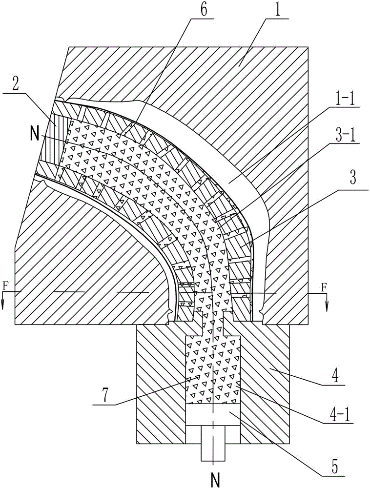
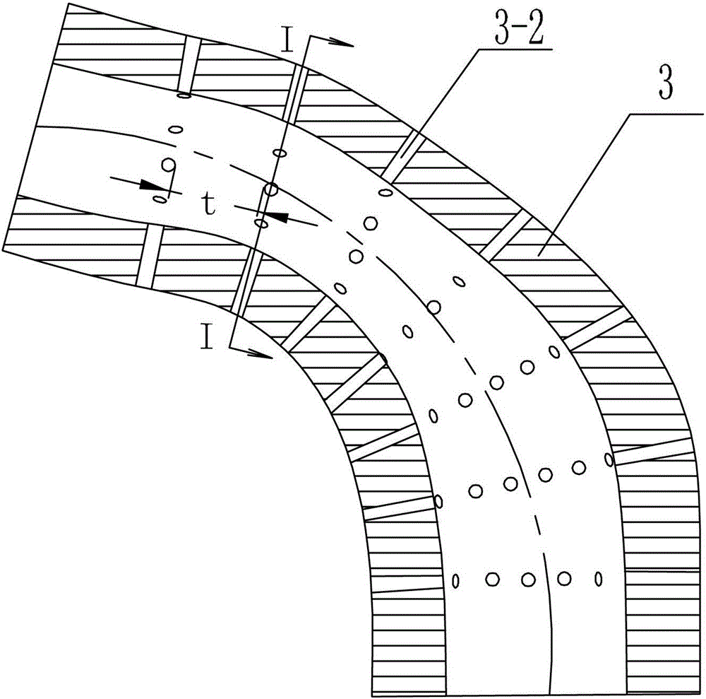
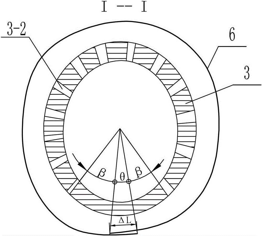
[0021] Specific implementation mode one: combine Figure 1 to Figure 11 Describe this embodiment, this embodiment comprises mold 1, plug 2, mandrel 3, medium storehouse 4 and plunger 5, the inside of mold 1 is provided with mold cavity 1-1, the mold cavity 1-1 The inlet end is located at the bottom of the mold 1, and the closed end of the mold cavity 1-1 is located at the side of the mold 1. The shape of the mold cavity 1-1 is a variable-section channel whose axis N-N of the mold cavity is a space curve, and the mold cavity 1 -1 The cross-sectional shape along the axial direction from the inlet end to the closed end successively transitions to a circle 1-3, a wide-short-axis ellipse 1-4, a narrow-short-axis ellipse 1-5, a waist shape 1-6, and a crescent shape 1-7 , the width minor axis b is greater than the narrow minor axis a, the two ends of the mold cavity 1-1 are provided with ring-shaped protrusions, the ring-shaped protrusions ensure that the annular non-closed blank 5 d...

specific Embodiment approach 2

[0022] Specific implementation mode two: combination Figure 6 The present embodiment will be described. The diameter of the circular 1-3 section in the present embodiment is 280 mm to 320 mm. This range can meet the design requirements of formed parts. Other components and connections are the same as those in the first embodiment.

specific Embodiment approach 3

[0023] Specific implementation mode three: combination Figure 7 Describe this embodiment, the cross-sectional dimensions of the wide and short axis ellipse 1-4 in this embodiment are: the width and major axis a on the wide and short axis ellipse 1-4 is 300 mm to 320 mm, and the width and short axis a on the wide and short axis ellipse 1-4 Axis b is 220 mm to 300 mm. This range can meet the design requirements of formed parts. Other compositions and connections are the same as those in Embodiment 1 or 2.


PUM

PropertyMeasurementUnit
thicknessaaaaaaaaaa
viscosityaaaaaaaaaa
diameteraaaaaaaaaa

Abstract

The invention provides a variable camber thin-walled part hoop flow forming device and method, and relates to the forming device and method of a variable camber thin-walled part with the axis as a space curve. The forming device and method solve the problem that a split forming method and a combined welding method are used for forming the variable camber thin-walled part with the axis as the space curve. According to the forming device, the shape of a mold cavity is a variable cross-section channel with the mold cavity axis as a space curve, the shapes of the cross sections of a section mold cavity from the inlet end to the closed end are sequentially a circular shape, a wide and short axis oval shape, a narrow and short axis oval shape, a kidney shape and a crescent moon shape, a core mold is arranged in the section mold cavity, a plurality of load injecting holes are formed in the side wall of the core mold, and a plunger is arranged in a soft mold cavity. The forming method comprises the steps that first, landing edge design is conducted on plate blank; second, the positions of the load injecting holes are designed; third, tubular plate blank is arranged between the core mold and a section mold; fourth, a visco-elastic plastic soft mold is injected into the soft mold cavity; fifth, the plunger is pushed to inject the visco-elastic plastic soft mold into the core mold cavity; sixth, the variable camber thin-walled part is taken out. The variable camber thin-walled part hoop flow forming device and method are used for forming the variable camber thin-walled part.

Description

technical field [0001] The invention relates to a forming method of a thin-walled part with a variable cross-section whose axis is a space curve, in particular to a method for forming a thin-walled part with a variable curvature in a circular flow. Background technique [0002] Thin-walled parts with variable cross-section whose axis is a space curve are a typical shell structure in the field of aerospace. Its main features and forming difficulties are that the uniformity of the wall thickness is high, the axis is a space curve, and the shape and size of the cross-section along the axis vary greatly. Transition to an elliptical cross-section, the major axis of the cross-section is 300mm-360mm, the short-axis is 120mm-300mm, the elliptical cross-section gradually transitions to a crescent-shaped cross-section, the radius of the inner arc of the cross-section is 70mm-110mm, and the radius of the outer arc is 340mm-380mm . At present, most of the thin-walled parts with variab...

Claims


Application Information

Patent Timeline
Patent Type & Authority Patents(China)
IPC IPC(8): B21D22/10
Inventor 王忠金易军袁斌先黄荆城
Owner HARBIN INST OF TECH
Why Eureka
Eureka Blog
Learn More