
Tool and method for fine machining of workpieces

A tool and workpiece technology, applied in the field of workpiece cutting and finishing, can solve the problems of insufficient tool life, lack of manufacturing accuracy of tools and methods, and inability to extend the axes of rotation precisely and coaxially with each other, to achieve precise dimensional accuracy and high surface The effect of smoothness and long tool life

Inactive Publication Date: 2009-07-29
MAPAL FAB FUR PRAZIONSWERKZEUGE DR KRESS KG
View PDF5 Cites 0 Cited by
  • Summary
  • Abstract
  • Description
  • Claims
  • Application Information

AI Technical Summary

Problems solved by technology

It is difficult that the axes of rotation of the individual tools do not run exactly coaxially with each other, so that sufficient manufacturing precision and the best possible surface finish cannot be achieved
[0009] So overall it shows that the tool and the method do not ensure sufficient manufacturing accuracy and the tool life is not sufficient

Method used


Image

  • Tool and method for fine machining of workpieces
  • Tool and method for fine machining of workpieces
  • Tool and method for fine machining of workpieces

Examples


Embodiment Construction

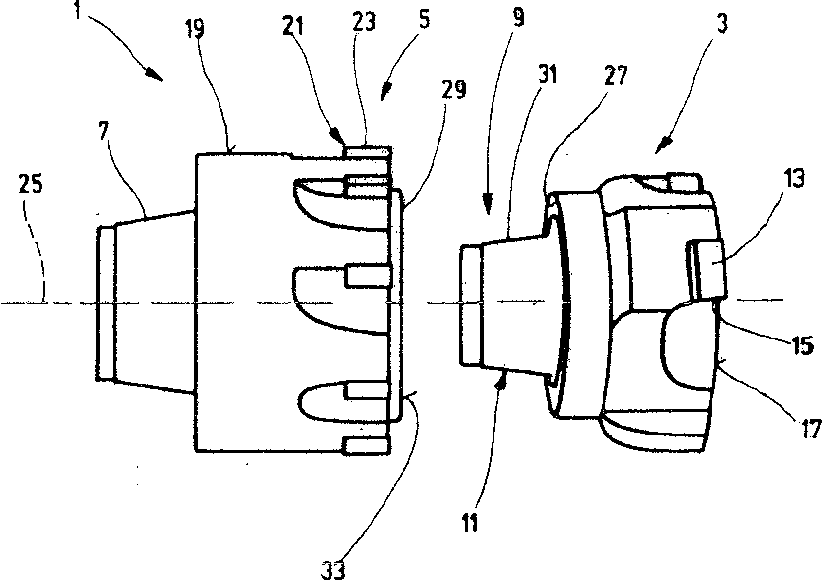
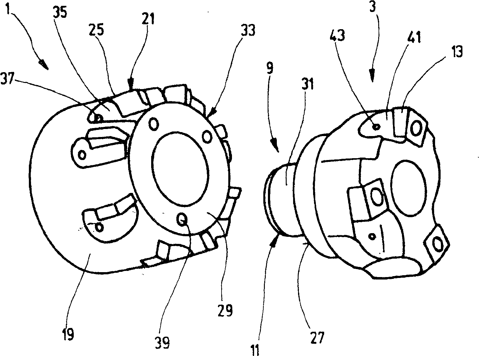
[0018] figure 1 A first exemplary embodiment of a tool 1 is shown which is used for the finishing machining of workpieces and which has a preliminary machining stage 3 and a finishing machining stage 5 .

[0019] The tool 1 can be connected in a suitable manner directly or via an intermediate piece, an adapter or the like to a machine tool, for example via a tapered shaft 7 which engages in a tool receiving hole and is clamped in a suitable manner therewith.

[0020] The preliminary machining stage 3 and the finishing machining stage 5 are fixedly connected to one another via a connection 9 which has a device 11 by means of which the relative position of the two stages can be influenced. It should set stages 3 and 5 coaxially with each other as much as possible. The interface 9 thus serves to connect the stages 3 and 5 of the tool 1 to each other such that the center axes of the two stages 3 and 5 coincide with each other and with the center axis 25 of the tool 1 . With the ...


PUM


Abstract

The invention relates to a cutting tool for finishing workpieces, comprising at least one insert (13) for preliminary machining with a geometrically defined cutting edge (15) and at least one insert (13) for final machining with a geometrically defined Define the cutting edge (23) of the blade (21). The tool is characterized in that the insert (13) for preliminary machining is a part of a preliminary machining stage (3) and the insert (21) for final machining is a part of a final machining stage (5), and a The interface (9) provided between the processing stage (3) and the final processing stage (5) is provided with a first planar surface (27) and a second planar surface (29), which are respectively arranged on the preliminary processing stage (3) and the final processing stage (5), and has a device (11) to ensure the coaxiality between the preliminary processing stage (3) and the final processing stage (5).

Description

technical field [0001] The invention relates to a tool for finishing machining of workpieces and a method for finishing machining of workpieces. Background technique [0002] Cutters and methods of the type described herein are known. The knife is characterized by a so-called graded blade, which includes a geometrically defined cutting edge. For finishing the workpiece, the tool and / or the workpiece are rotated and displaced axially in the direction of the axis of rotation, so that the cutting edge removes chips from a surface of the workpiece to be machined. The workpiece is generally clamped, while the tool is rotated and performs a feed movement. The cutting edge thereby removes chips from one surface of the workpiece. [0003] The front stage of the staged inserts in the feed direction is used for rough machining or preliminary machining of the workpiece surface and the latter stage is used for finishing or final machining of the workpiece surface. Grading blades are...

Claims


Application Information

Patent Timeline
Patent Type & Authority Patents(China)
IPC IPC(8): B23B51/00B23C5/00B23B41/16B23B51/08B23D77/00
CPCB23C5/006B23B2265/08Y10T29/49996Y10T409/303808Y10T82/2585Y10T29/5168Y10T409/307168Y10T408/03Y10T29/5147Y10T409/30952Y10T82/10B23C2220/605B23B51/009Y10T408/906Y10T409/307784B23B51/08B23B51/00B23B41/16
Inventor D·克雷斯F·黑贝勒
Owner MAPAL FAB FUR PRAZIONSWERKZEUGE DR KRESS KG
Learn More