AI technical title is built by PatSnap AI team. It summarizes the technical point description of the patent document.
A technology for assembling and welding tires and molds, which is applied in welding equipment, manufacturing tools, auxiliary welding equipment, etc., can solve the problem of not being able to freely adjust the distance between welding molds for motor movers, reducing the service life of welding molds for motor movers, Solve the problems such as shaking and damage of the welding mold of the motor mover group, and achieve the effect of simple structure, small error, and avoiding shrinkage and impact damage
Active Publication Date: 2021-09-07
HEILONGJIANG HENGYI ELECTRICAL SHARE CO LTD
View PDF5 Cites 0 Cited by
Summary
Abstract
Description
Claims
Application Information
AI Technical Summary
This helps you quickly interpret patents by identifying the three key elements:
Problems solved by technology
Method used
Benefits of technology
Problems solved by technology
[0002] The motor mover refers to an electromagnetic device that realizes the conversion or transmission of electric energy according to the law of electromagnetic induction; its main function is to generate driving torque as a power source for electrical appliances or various machines. Generally, the motor mover adopts the motor mover group Welding molds are used for processing and production; traditional motor mover processing and production assembly welding requires the output rod to be aligned with an angle ruler after assembly, which is time-consuming, material-intensive, labor-intensive, and costly; the assembly error deviation is large in each assembly At the same time, the motor mover group welding mold is traditionally fixed manually, the fixation is extremely weak, and the installation and disassembly are troublesome, which is not conducive to the user's access to the motor mover. The size of the motor mover is fixed and processed, and there is no protection device. External impacts can easily cause shaking damage to the welding mold of the motor mover group and reduce the service life of the welding mold of the motor mover group. To address these defects, a motor mover is designed It is necessary to assemble the welding mold
Method used
Image
Click on the blue label to locate the original text in one second.
Reading with bidirectional positioning of images and text.
Examples
Embodiment Construction
[0024] The following will clearly and completely describe the technical solutions in the embodiments of the present invention with reference to the accompanying drawings in the embodiments of the present invention. Obviously, the described embodiments are only some, not all, embodiments of the present invention. Based on the embodiments of the present invention, all other embodiments obtained by persons of ordinary skill in the art without making creative efforts belong to the protection scope of the present invention.
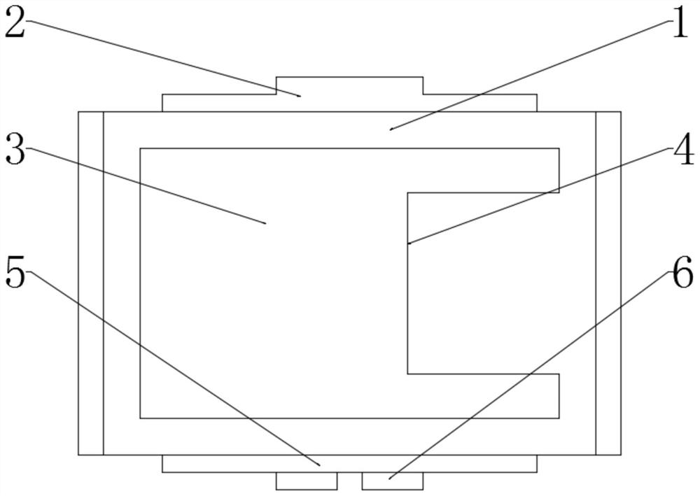
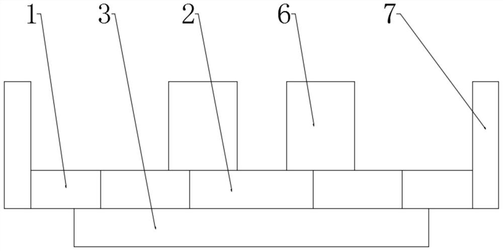
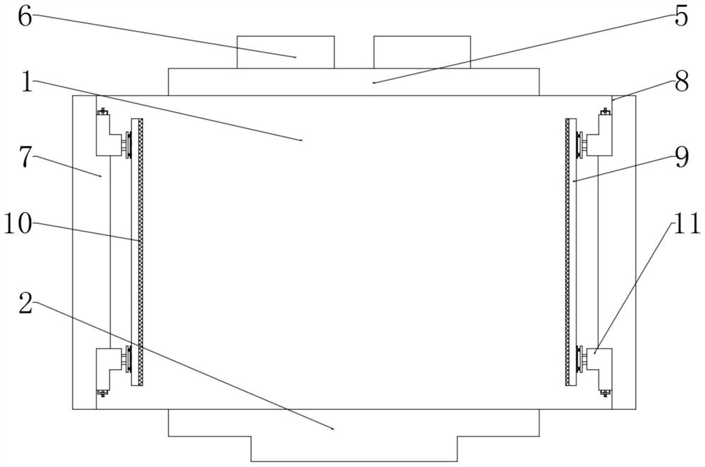
[0025] see Figure 1-6 , the present invention provides a technical solution: a motor mover assembly welding mold, including a mold workbench 1, a mold convex block 2, a mold base 3, a slot 4, a connecting block 5, a back plate 6, Side plate 7, fixed groove 8, extrusion block 9, heat-resistant anti-skid pad 10, pressure box 11, first partition 12, extrusion rod 13, side hole 14, moving plate 15, buffer pad 16, ball 17, stopper Plate 18, threaded column 19, fi...
PUM
Abstract
The invention discloses a welding mold of electric mover, which comprises mold working table, mold convex block, mold base, card groove, connection block, back plate, side plate, fixing groove, extrusion block, resistant Thermal anti-skid pad, pressure box, first partition, extrusion rod, side hole, moving plate, buffer pad, ball, baffle, threaded column, first self-locking nut, fixed frame, second self-locking nut, threaded hole , a second partition, a gasket, a first spring plate, a second spring plate and a reinforcement plate, the mold base is welded to the bottom of the mold workbench, and a slot is provided at one end of the mold base, and the mold base Both sides of the workbench are welded with side plates, and the surface of the mold workbench is welded with mold convex blocks. The motor mover assembly welding mold uses wire cutting to process the required steel plates for assembly and welding, and the dimensional accuracy of the processed parts is The high error is small, and the secondary processing after welding can ensure the required verticality, parallelism, and more accurate dimensional error.
Description
technical field [0001] The invention relates to the technical field of electric movers, in particular to an electric mover assembly welding mold. Background technique [0002] The motor mover refers to an electromagnetic device that realizes the conversion or transmission of electric energy according to the law of electromagnetic induction; its main function is to generate driving torque as a power source for electrical appliances or various machines. Generally, the motor mover adopts the motor mover group Welding molds are used for processing and production; traditional motor mover processing and production assembly welding requires the output rod to be aligned with an angle ruler after assembly, which is time-consuming, material-intensive, labor-intensive, and costly; the assembly error deviation is large in each assembly At the same time, the motor mover group welding mold is traditionally fixed manually, the fixation is extremely weak, and the installation and disassembl...
Claims
Application Information
Patent Timeline
Application Date:The date an application was filed.
Publication Date:The date a patent or application was officially published.
First Publication Date:The earliest publication date of a patent with the same application number.
Issue Date:Publication date of the patent grant document.
PCT Entry Date:The Entry date of PCT National Phase.
Estimated Expiry Date:The statutory expiry date of a patent right according to the Patent Law, and it is the longest term of protection that the patent right can achieve without the termination of the patent right due to other reasons(Term extension factor has been taken into account ).
Invalid Date:Actual expiry date is based on effective date or publication date of legal transaction data of invalid patent.

