Miniaturized helium photoionization detector

a detector and helium technology, applied in the field of miniaturized helium photoionization detectors, can solve the problems of insufficient implementation and application of sorptive and thermal sensing detectors, inability to achieve comparable detection levels, and inability to miniaturize them

Active Publication Date: 2018-08-14
VIRGINIA TECH INTPROP INC
View PDF11 Cites 1 Cited by
  • Summary
  • Abstract
  • Description
  • Claims
  • Application Information

AI Technical Summary

Benefits of technology

[0010]Unlike the above-described devices, some embodiments of the present invention provide a sensitive, low-power, easy-to-fabricate universal detector that utilizes a microdischarge. The embodiments utilize high-energy photons and excited state helium metastable species to ionize the analytes. The resultant current is monitored on a remote sensing or collector electrode.

Problems solved by technology

It should be noted that while ionization detectors such as the FID provide robust performance and sensitivity, efforts to miniaturize them do not yield comparable detection levels since the hydrogen flame loses its ionizing potential when reduced in size.
On the other hand, sorptive and thermal sensing detectors have inherent limitations since they are more temperature sensitive and hence their implementation and application has been inadequate as well.
This has resulted in dimensions slightly larger than that found in μGC and a power dissipation on the order of tens of watts.
These systems offer excellent detection sensitivity, but are somewhat restricted by the photoionization energies available (<11.7 eV with argon lamps) as well as incorporation into a μGC system.
However, spectrophotometric detection is an intensive operation that consumes power on the order of watts.
However, a common concern with these designs is the fouling of the electrodes due to fragmentation of the analytes.
Fragmentation also does not allow for the analytes to be subjected to further analysis.

Method used


Image

  • Miniaturized helium photoionization detector
  • Miniaturized helium photoionization detector
  • Miniaturized helium photoionization detector

Examples


Embodiment Construction

[0028]Detailed embodiments of the present invention are disclosed herein; however, it is to be understood that the disclosed embodiments are merely exemplary of the invention, which may be embodied in various forms. Therefore, specific structural and functional details disclosed herein are not to be interpreted as limiting, but merely as a representative basis for teaching one skilled in the art to variously employ the present invention in virtually any appropriately detailed method, structure or system. Further, the terms and phrases used herein are not intended to be limiting, but rather to provide an understandable description of the invention.

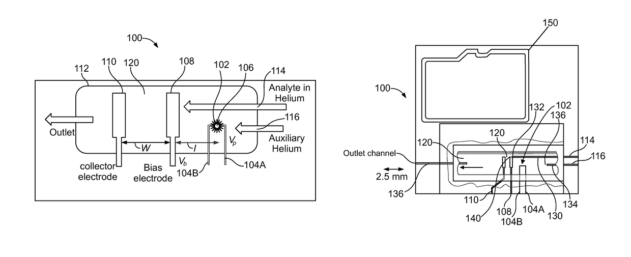
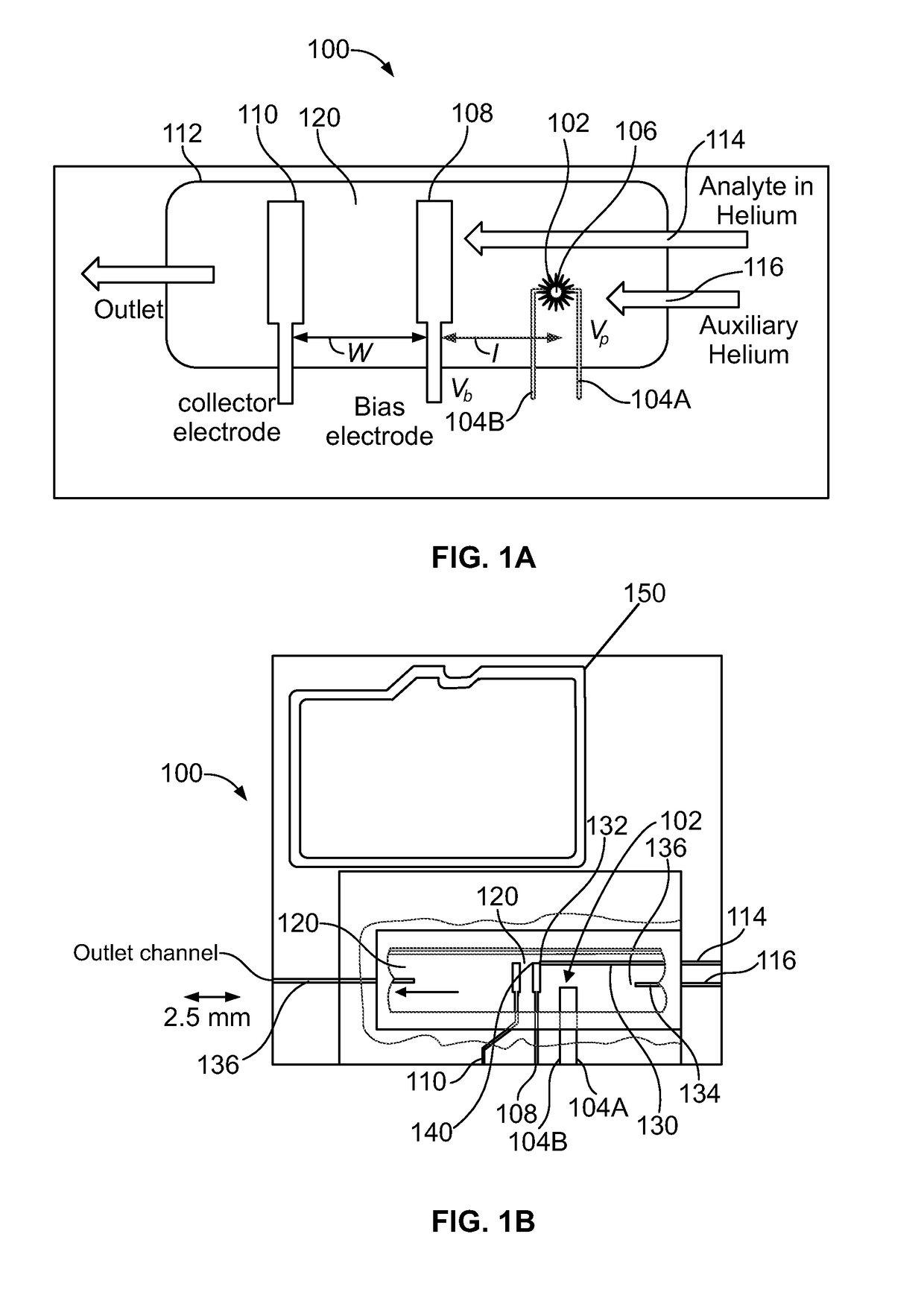
[0029]As shown in FIGS. 1A and 1B, some embodiments of the present invention provide a micro-helium discharge ionization detector (μHDID) 100 that is an ionization style detector that operates by measuring the resultant current from the ionization of the analytes without molecular fragmentation. Detector 100 utilizes a high voltage DC disch...


PUM

PropertyMeasurementUnit
voltageaaaaaaaaaa
voltageaaaaaaaaaa
depthaaaaaaaaaa

Abstract

The present invention provides an ionization detector having a base having an enclosed chamber. The enclosed chamber has a first end and a second end. The detector also includes a first outlet which is a source of an excitable medium. A second outlet is provided which functions a source of an analyte that is transported by a carrier gas. An ionization source for creating a discharge from said excitable medium is also provided. The collector electrode generates a time dependent current based on its interaction with ionized analytes from which the analyte may be detected.

Description

RELATED APPLICATIONS[0001]This application claims the benefit of U.S. Provisional Application No. 61 / 898,861, filed Nov. 1, 2013.STATEMENT REGARDING FEDERALLY SPONSORED RESEARCH & DEVELOPMENT[0002]This invention was made with government support under Grant No. ECCS0747600 awarded by the National Science Foundation and Grant No. R21_OH010330 awarded by the Centers for Disease Control and Prevention. The government has certain rights in the invention.INCORPORATION BY REFERENCE OF MATERIAL SUBMITTED ON A COMPACT DISC[0003]Not applicable.BACKGROUND OF THE INVENTION[0004]Micro gas chromatography (μGC) is based on developing miniaturized, portable systems capable of identifying the composition of a gas mixture by separation into its individual components and are applicable for homeland security, space exploration, on-site or distributed environmental monitoring mechanisms, and food assessment. In a typical μGC system, the sample mixture is first collected on an adsorbent bed referred to a...

Claims


Application Information

Patent Timeline
Patent Type & Authority Patents(United States)
IPC IPC(8): G01N27/66G01N27/68
CPCG01N27/68
Inventor AGAH, MASOUDSREEDHARAN NAIR, SHREE NARAYANAN
Owner VIRGINIA TECH INTPROP INC
Why Eureka
Try Eureka