System and method for testing a device-under-test

a technology of a system and a test method, applied in the field of systems, can solve problems such as slow testing path, and achieve the effect of efficient excitation

Active Publication Date: 2021-11-11
ROHDE & SCHWARZ GMBH & CO KG
View PDF0 Cites 0 Cited by
  • Summary
  • Abstract
  • Description
  • Claims
  • Application Information

AI Technical Summary

Benefits of technology

The patent text describes a device or system that can evaluate a device under test (DUT) quickly and without physical contact. This makes it easy to test and measure the device's performance. Additionally, the medium (the material being tested) can be excited efficiently, which helps to create certain states of matter.

Problems solved by technology

However, this way of testing can be slow, because each PCB must be connected and disconnected from the test rig, and requires additional equipment.

Method used


Image

  • System and method for testing a device-under-test
  • System and method for testing a device-under-test
  • System and method for testing a device-under-test

Examples


Embodiment Construction

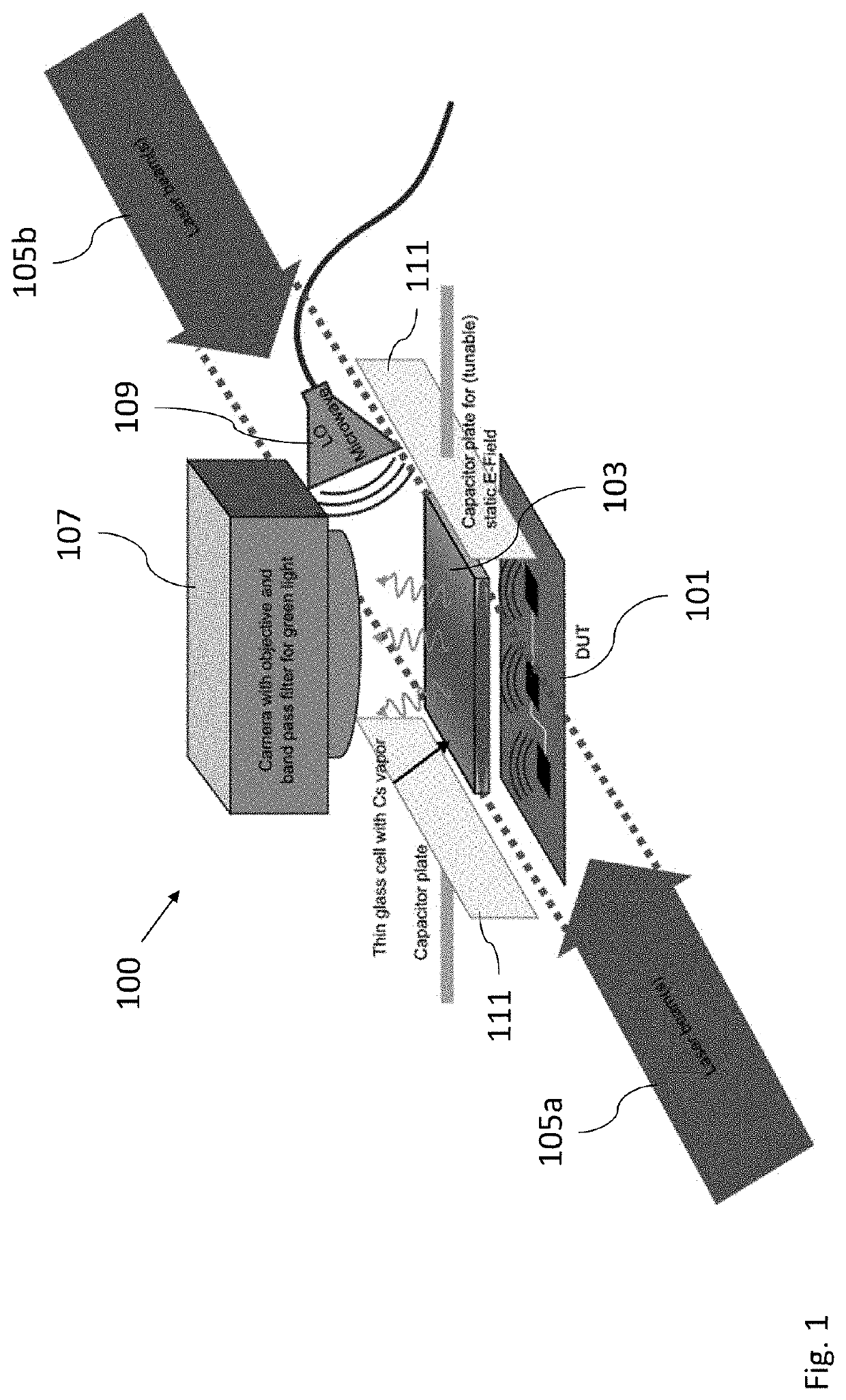
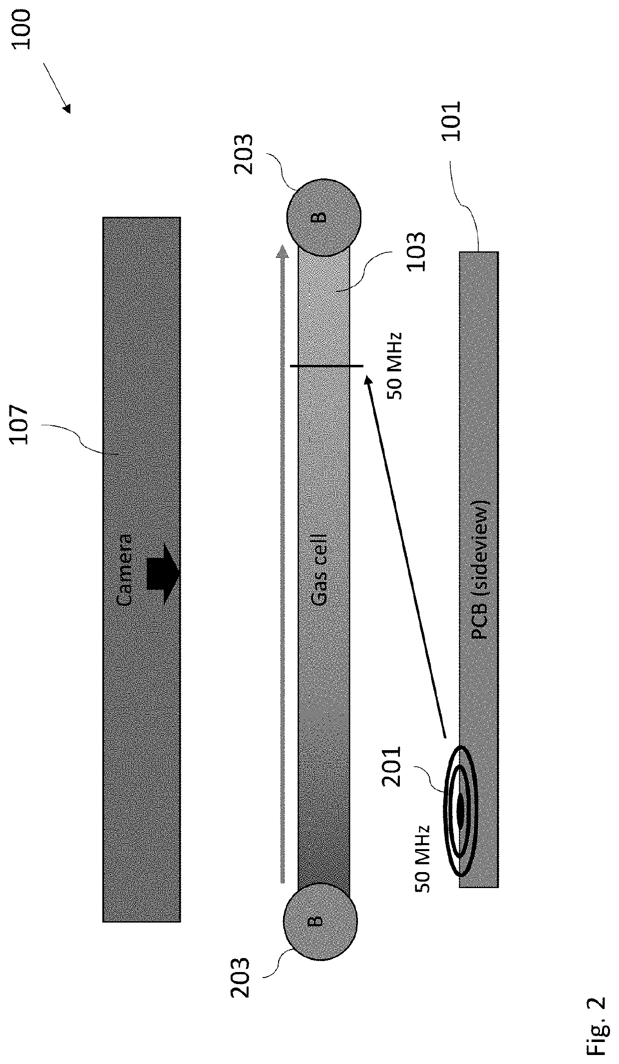
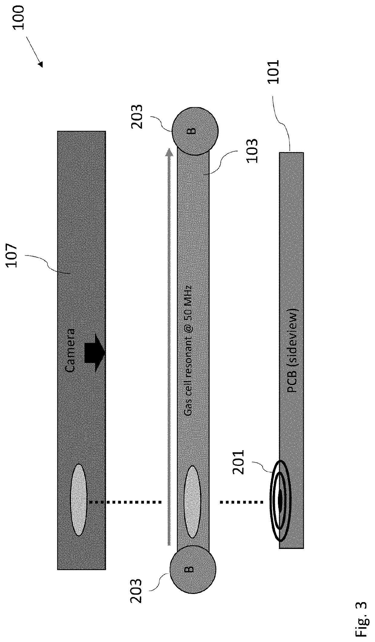
[0071]FIG. 1 shows a schematic diagram of a system 100 for testing a DUT 101 according to an embodiment.

[0072]The system 100 comprises an optically excitable medium 103 which is arranged to receive EM radiation emitted by the DUT 101, at least one light source configured to irradiate the medium with at least one light beam 105a, 105b, wherein the medium 103 is optically excited by the at least one light beam 105a, 105b, and a field generator unit configured to generate an electric and / or magnetic field within the medium, wherein a resonance frequency of the excited medium 103 is modified by an amplitude of the electric and / or magnetic field, and wherein an optical parameter, in particular a luminescence, of the exited medium 103 is locally modified if a frequency of the EM radiation corresponds to the resonance frequency at a position in the medium 103. The system 100 further comprises an image detector 107 configured to acquire an image of the medium 103, wherein the image shows an...


PUM

PropertyMeasurementUnit
frequencyaaaaaaaaaa
wavelengthaaaaaaaaaa
resonance frequencyaaaaaaaaaa

Abstract

The invention relates to a system in particular a quantum sensor system, for testing a device-under-test, DUT, comprising: an optically excitable medium which is arranged to receive electromagnetic, EM, radiation emitted by the DUT, at least one light source configured to irradiate the medium with at least one light beam, wherein the medium is optically excited by the at least one light beam, a field generator unit configured to generate an electric and / or magnetic field within the medium, wherein a resonance frequency of the excited medium is modified by an amplitude of the electric and / or magnetic field, wherein an optical parameter, in particular a luminescence, of the exited medium is locally modified if a frequency of the EM radiation corresponds to the resonance frequency at a position in the medium, an image detector configured to acquire an image of the medium, wherein the image shows an intensity profile that results from the modification of the optical parameter, a processor configured to analyze the DUT based on the acquired image.

Description

TECHNICAL FIELD OF THE INVENTION[0001]The invention relates to a system, in particular a quantum sensor system, and a method for testing a device-under-test.BACKGROUND OF THE INVENTION[0002]Many electronic devices undergo testing at first manufacture or later during their life cycles. During testing, such devices are typically referred to as device-under-test (DUT).[0003]For example, printed circuit boards (PCBs) are usually tested at some point during a production process to identify and remove PCBs which have a defect. Ideally, this testing is carried out as quickly as possible, for instance while the PCBs are on an assembly line, to avoid delaying the production process.[0004]In a typical testing scheme, the device is connected to a test rig via a wire in order to test various device functionalities. However, this way of testing can be slow, because each PCB must be connected and disconnected from the test rig, and requires additional equipment.[0005]PCBs are often designed to em...

Claims


Application Information

Patent Timeline
Patent Type & Authority Applications(United States)
IPC IPC(8): G01R31/28G01R1/07
CPCG01R31/281G01R1/071G01R31/2806G01R31/309
Inventor WINKLER, THOMASRUSTER, THOMASLEONG, RYANNE
Owner ROHDE & SCHWARZ GMBH & CO KG
Why Eureka
Try Eureka