LED lamp using blue and cyan LEDs and a phosphor

a technology of led lamps and leds, which is applied in the field of phosphor-converted led lamps, can solve the problems of inability to meet the requirements add significant expense, and produce relatively poor color rendering of dichromatic light sources, and achieve the effects of increasing the cri of light emission, reducing the cost of lighting and heating equipment, and efficient excitation

Active Publication Date: 2014-12-09
NTHDEGREE TECH WORLDWIDE
View PDF4 Cites 21 Cited by
  • Summary
  • Abstract
  • Description
  • Claims
  • Application Information

AI Technical Summary

Benefits of technology

[0009]In one embodiment, thousands of micro-LEDs (e.g., 25 microns per side) are deposited on a substrate, and electrical connections are made using a transparent conductor layer. Some of the LEDs are formed to emit a peak wavelength of 450 nm (blue), and some are formed to emit a peak wavelength of 490 nm (cyan). The two types of LEDs are GaN based and can be driven at the same current. The two types of LEDs react similarly to heat. The ratio of the two types of LEDs is controlled to achieve the desired overall color emission of the LED lamp. In one embodiment, a yellow phosphor, such as YAG, is then deposited on the LEDs, or a remote yellow phosphor layer is used. YAG phosphor is most efficiently excited at 450 nm and has a very weak emission at 490 nm. The blue LED efficiently excites the yellow phosphor to produce white light having blue and yellow components, and the cyan LED adds a green component to increase the CRI of the light emission and luminous efficiency.
[0011]In another embodiment, the relatively broad emission YAG phosphor is not used. Instead, a combination of red and non-YAG yellow phosphors are deposited at least over the blue LEDs or used remotely. The blue wavelength is optimized for the phosphor. The cyan LEDs, which may not be covered by any phosphor, obviates the need for a green phosphor to broaden the spectrum, improving the efficiency of the lamp and improving color consistency.
[0012]This dual LED approach has been shown to improve luminous efficiency and generate a higher CRI due to the broader spectrum generated. Improving the luminous efficiency is due to lower phosphor usage and generating an emission that better conforms to the luminous efficiency function of the human visual system.
[0018]The lamp is engineered for the warmest CCT, such as 2700K. Then, by increasing the amount of blue and / or cyan, the color is cooled to higher CCTs. For example, at one setting, the lamp may produce a CCT of 2700K with a CRI of 94 and a LER of 288 lm / W. Then, by increasing the current to the blue and / or cyan LEDs not covered by the phosphor, the light can be cooled to 4000K or 6000K, for example. All points on the Planckian locus may be possible. Dynamically adjusting the light throughout the day for a circadian rhythm is achievable.
[0021]The 490 nm LEDs may be replaced with GaN LEDs emitting a longer peak wavelength (closer to green), such as 507 nm, to obtain a high scotopic response, since the scotopic response typically peaks at 507 nm. This would result in the lamp appearing brighter than actually measured. In other words, it would increase the pupil lumens.
[0023]Thus, by using the inventive technique, there is less energy loss due to phosphor conversion, the luminous efficacy is improved, the CRI is increased, and the color can be controlled.

Problems solved by technology

However, such LEDs are fabricated using special techniques that add significant expense, making them not yet commercially viable.
Such a di-chromatic light source produces relatively poor color rendering, since the highest color rendering is produced with a broad-spectrum source, such as the sun or a radiating black body.
However, combining and depositing phosphors to produce a consistent emitted color is difficult.
Phosphors are also relatively expensive and reduce the efficiency of the LED.
Another problem with phosphors is that the color cannot be controlled once the phosphor is deposited over the LED.
Accordingly, such LED modules have better CRI but lack color stability and are expensive.

Method used


Image

  • LED lamp using blue and cyan LEDs and a phosphor
  • LED lamp using blue and cyan LEDs and a phosphor
  • LED lamp using blue and cyan LEDs and a phosphor

Examples


Embodiment Construction

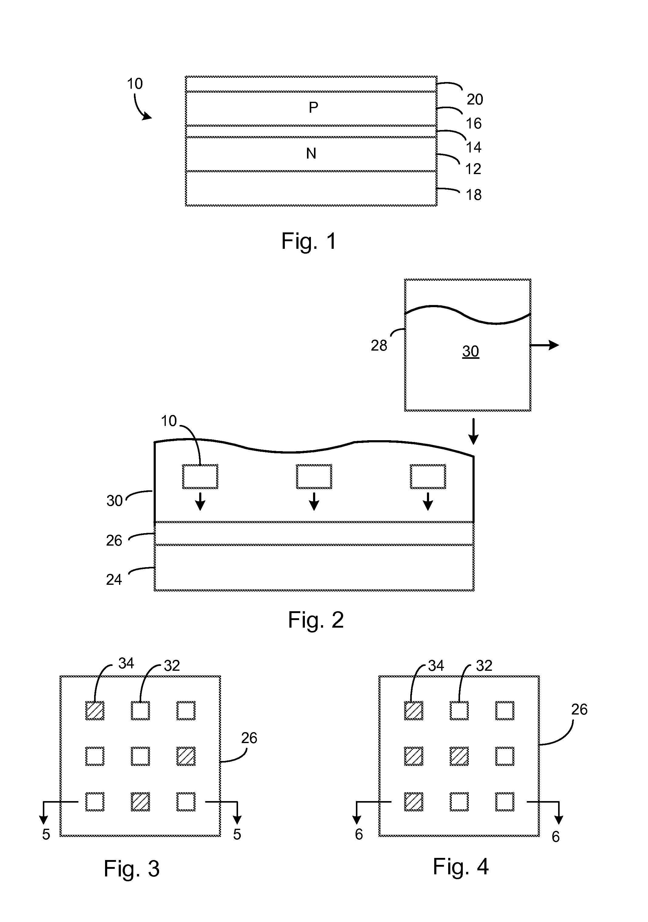
[0039]FIG. 1 is a cross-sectional view of a micro-LED chip 10 emitting a peak wavelength of either 450 nm or 490 nm, depending on the structure of its active layer. The LED chip 10 is manufactured as part of a wafer containing many thousands of LEDs. The wafer may be broken along etched lines into small LED chips with sides approximately 25 microns. Since the growth substrate is removed, the chip 10 may be only a few microns thick, such as 3-10 microns thick. Forming GaN-based LEDs to emit light with peak wavelengths of 450 nm and 490 nm is well known.

[0040]Typically, the GaN-based LED semiconductor layers are grown on a sapphire substrate or other suitable growth substrate. N-type layers 12 are epitaxially grown, followed by an active layer 14, followed by p-type layers 16. The growth substrate is then removed, and ohmic contact to the n-type layers 12 is made by depositing a large, reflective metal alloy (or multiple metal layers) on the n-layers 12 to form a bottom electrode 18. ...


PUM


Abstract

Many thousands of micro-LEDs (e.g., 25 microns per side) are deposited on a substrate. Some of the LEDs are formed to emit a peak wavelength of 450 nm (blue), and some are formed to emit a peak wavelength of 490 nm (cyan). A YAG (yellow) phosphor is then deposited on the LEDs, or a remote YAG layer is used. YAG phosphor is most efficiently excited at 450 nm and has a very weak emission at 490 nm. The two types of LEDs are GaN based and can be driven at the same current. The ratio of the two types of LEDs is controlled to achieve the desired overall color emission of the LED lamp. The blue LEDs optimally excite the YAG phosphor to produce white light having blue and yellow components, and the cyan LEDs broaden the emission spectrum to increase the CRI of the lamp while improving luminous efficiency. Other embodiments are described.

Description

FIELD OF THE INVENTION[0001]This invention relates to phosphor-converted (PC) light emitting diode (LED) lamps that generate white light and, more particularly, to a PC LED lamp that uses LEDs emitting at two different peak wavelengths to improve the color rendering and luminous efficacy of the lamp.BACKGROUND[0002]Commercially available LEDs typically emit a single color (peak wavelength). Some experimental LED chips have been produced that can produce multiple peak wavelengths. However, such LEDs are fabricated using special techniques that add significant expense, making them not yet commercially viable.[0003]The most common white-light LED uses a 450 nm blue LED that excites a relatively broad emission YAG:Ce phosphor deposited over the LED. The peak emission wavelength of YAG is about 535-565 nm (yellow-green). The blue light leaks through the YAG layer, and the combination of the blue and yellow light (phosphor converted blue light) creates white light. Such a di-chromatic lig...

Claims


Application Information

Patent Timeline
Patent Type & Authority Patents(United States)
IPC IPC(8): H01L21/00
CPCH01L25/0753H01L33/502H01L2924/0002H01L2924/00
Inventor RETTKE, REUBEN
Owner NTHDEGREE TECH WORLDWIDE
Why Eureka
Try Eureka