Solar cell apparatus and method for manufacturing same

a solar cell and apparatus technology, applied in photovoltaic supports, pv power plants, sustainable buildings, etc., can solve the problems of inability to bring the solar cell unit into close contact with the portion to be installed, inability to achieve the effect of reducing the light reflectivity, not easily stained, and increasing the power generation of the solar cell uni

Inactive Publication Date: 2018-08-14
PANASONIC INTELLECTUAL PROPERTY MANAGEMENT CO LTD
View PDF24 Cites 1 Cited by
  • Summary
  • Abstract
  • Description
  • Claims
  • Application Information

AI Technical Summary

Benefits of technology

[0022]As described above, in the solar cell device of the present invention, an airtight space is formed by the translucent plastic material and the fixing target, to allow the double-sided light-receiving solar cell unit to be placed in the airtight space. Therefore, the solar cell unit placed in the airtight space is not easily stained even when the solar cell device is installed outdoors. In addition, since the translucent plastic material and the fixing target can form the airtight space, a rack or a frame body to be used exclusively for fixing the solar cell device is not required.
[0023]In addition, the light reflector provided on the surface of the installing area of the fixing target where an airtight space is formed enables light reflected at the surface of the installing area of the fixing target to enter the double-sided light-receiving solar cell unit, thereby allowing the amount of power generation by the solar cell unit to be increased. Further, since the airtight space is configured not to allow the stain due to wind and rain or dust to enter the airtight space, light reflectivity is not decreased. Therefore, it is possible to limit the decrease in the amount of power generation by the solar cell unit.
[0024]Thus, the solar cell device of the present invention allows the amount of power generation of the solar cell unit to be higher and the power generation efficiency per unit area to be higher, and is configured not to allow the stain due to wind and rain or dust to enter the airtight space in which the solar cell unit is disposed. Therefore, the solar cell device of the present invention can be used as a member for closing the interior of an automobile or the interior of a house airtight.

Problems solved by technology

When the solar cell device illustrated in FIG. 14 is tried to be fixed to an automobile roof, a tile-integrated or building material-integrated house, a ship, and the like, a gap occurs between a mounting portion of the solar cell device and a portion to be installed, making it difficult to bring it into close contact with the portion to be installed.
As a result, wind and rain sometimes enter a space occurring between the mounting portion of the solar cell device and the fixing target.
In addition, there occurs a useless space.
Further, there is also a problem of impaired outer appearance.
However, the solar cell device including the translucent member having the curved surface structure lacks flexural strength at a location with smaller curvature radius of the translucent member, causing the problem of cracks or fractures easily occurring in the solar cell unit.
As a result, there occurs a problem of increasing fuel consumption of an automobile having the solar cell device mounted on the automobile roof.

Method used


Image

  • Solar cell apparatus and method for manufacturing same
  • Solar cell apparatus and method for manufacturing same
  • Solar cell apparatus and method for manufacturing same

Examples


embodiment 1

[0049][Embodiment 1]

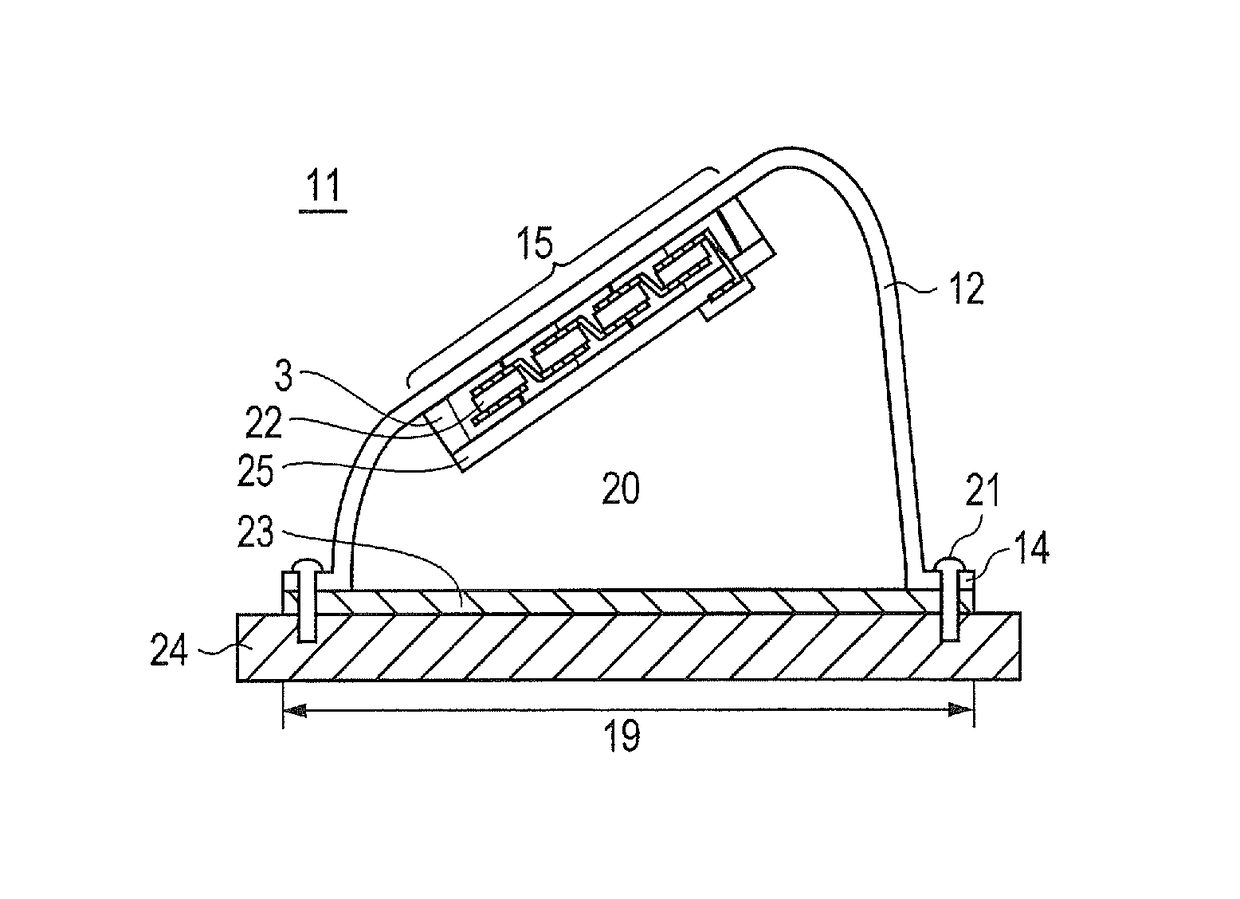
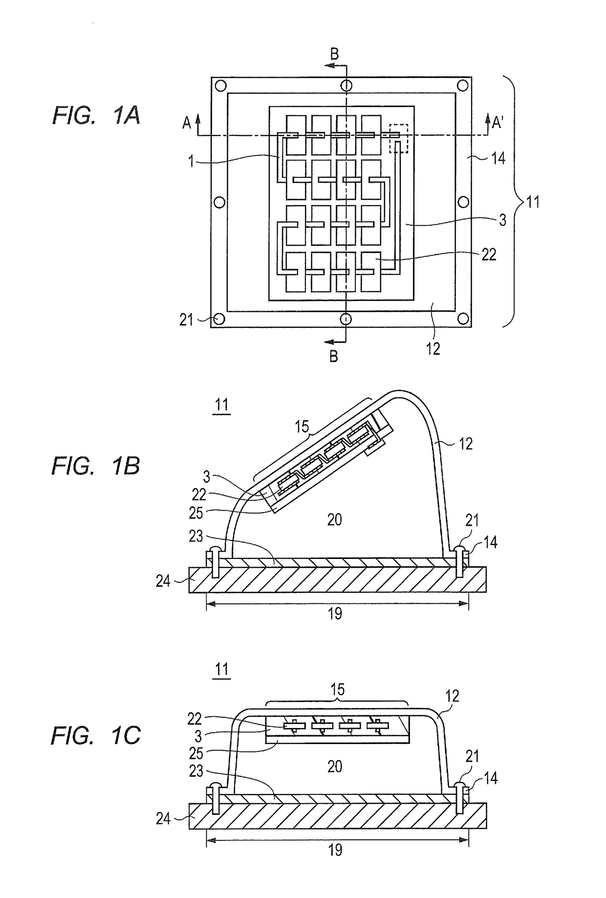
[0050]FIGS. 1A to 1C are a top view (FIG. 1A) and sectional views (FIG. 1B (A-A sectional view in FIG. 1A) and FIG. 1C (B-B sectional view in FIG. 1A)) of the solar cell device of Embodiment 1. Solar cell device 11 illustrated in FIGS. 1A to 1C includes a plurality of double-sided light-receiving solar cell units 22. Solar cell units 22 adjacent to each other are electrically connected in series by electrically connecting a light-receiving electrode on the front side of one solar cell unit 22 to a light-receiving electrode on the rear side of the other solar cell unit 22 through interconnector 1. In addition, solar cell device 11 illustrated in FIGS. 1A to 1C includes transparent filling resin 3 that surrounds a plurality of solar cell units 22.

[0051]Further, solar cell device 11 illustrated in FIGS. 1A to 1C includes translucent plastic material 12 disposed on the light-receiving surface side of a plurality of solar cell units 22 that perform double-sided power ...

embodiment 2

[0111][Embodiment 2]

[0112]FIG. 7 illustrates a solar cell device of Embodiment 2. The solar cell device of Embodiment 2 has concave curved surface 12a being concave with respect to the outer space, at a portion other than sealing area 15 (side surface portion) of translucent plastic material 12 of solar cell unit 22. Providing concave curved surface 12a at the side surface portion enables the area of installing area 19 to be smaller than the area of sealing area 15 for solar cell unit 22. When the area of installing area 19 is set smaller, it becomes possible to increase ratio of the area of sealing area 15 for solar cell unit 22 to the area of fixing target 24. As a result, the efficiency in installing the solar cell device is enhanced.

[0113]In addition, providing concave curved surface 12a at the side surface portion of translucent plastic material 12 allows the incident angle of sunlight 37 reflected at the surface of fixing target 24 outside installing area 19 into the side surf...

embodiment 3

[0114][Embodiment 3]

[0115]FIG. 8 illustrates a solar cell device of Embodiment 3. The solar cell device of Embodiment 3 has convex curved surface 12b being convex with respect to the outer space, at the surface of sealing area 15 of translucent plastic material 12 for solar cell unit 22. Providing convex curved surface 12b at sealing area 15 for solar cell unit 22 allows the rigidity of the solar cell device to be enhanced. In addition, it is also possible to bring the incident angle of sunlight into the surface of sealing area 15 for solar cell unit 22 closer to right angle by adjusting the surface angle of convex curved surface 12b. Thus, in spite of the change in the altitude of the sun throughout a year and of the movement of the sun throughout a day, it is possible to constantly reduce the reflectance on the surface of sealing area 15 for solar cell unit 22, and thus to increase the amount of power generation of solar cell unit 22.

[0116]In the same manner as the solar cell devi...


PUM


Abstract

A solar cell apparatus in which contamination of solar cells is suppressed and a power generation quantity of the solar cells is maintained for a long period of time, even if the solar cell apparatus is disposed outside. The apparatus is provided with: a light transmitting plastic material; a light transmitting back sheet; a plurality of bifacial solar cells that are electrically connected to each other by means of interconnectors; and a transparent filled resin that surrounds the solar cells. The light transmitting plastic material has a curved surface, and is capable of constituting a hermetically closed space by being fixed to a disposition region of a body having the solar cell apparatus disposed thereon. The light transmitting back sheet, the solar cells, and the transparent filled resin are disposed in the hermetically closed space.

Description

BACKGROUND OF THE INVENTION[0001]1. Technical Field[0002]The present invention relates to a solar cell device including a translucent plastic material having a curved surface, and a manufacturing method thereof.[0003]2. Description of the Related Art[0004]Recently, solar cells have attracted much interest as clean energy sources. In particular, silicon solar cells, which have higher power generation efficiency, have been taken into consideration as the most potential power for high-end markets for housing, automobiles, and the like in terms of various installation methods and construction sites. A solar cell typically has solar cell units and a translucent member, and light having passed through the translucent member enters the solar cell unit.[0005]Most of mainstream solar cell devices currently provided have a flat-shaped translucent member. That is, as illustrated in FIG. 15, planar stack 6 of a solar cell device including solar cell units 2 is fixed to a fixing target with fram...

Claims


Application Information

Patent Timeline
Patent Type & Authority Patents(United States)
IPC IPC(8): H01L31/048H02S10/40H02S30/10H02S20/22H02S20/30H01L31/054H01L31/0747H02S20/00H02S40/22H02S20/10H01L31/18
CPCH01L31/048H01L31/0543H01L31/0547H01L31/0747H01L31/18H02S10/40H02S20/10H02S20/22H02S20/30H02S30/10H02S40/22H02S20/00Y02E10/52Y02B10/10
Inventor NOBORI, KAZUHIRO
Owner PANASONIC INTELLECTUAL PROPERTY MANAGEMENT CO LTD
Why Eureka
Try Eureka