Continuously variable transmission and bicycle with the same

A technology of continuously variable transmissions and bicycles, which is applied to vehicle gearboxes, vehicle components, chain/belt transmissions, etc., and can solve problems such as the need for further improvement in stability and reliability, complex installation structure of transmissions, and unclosed transmission systems, etc. Achieve the effect of simple structure, convenient installation and small size

Inactive Publication Date: 2017-02-22
吕元胜
View PDF4 Cites 0 Cited by
  • Summary
  • Abstract
  • Description
  • Claims
  • Application Information

AI Technical Summary

Problems solved by technology

Although the continuously variable transmission mechanism can reduce the loss between the components during transmission and make the power transmission more reliable at the same time, its structure is relatively complicated, and the stability and reliability of the transmission need to be further improved.
[0003] The existing variable-speed bicycles are equipped with speed change devices, most of which are gear speed change devices, that is, the purpose of speed change is achieved by changing the size and number of teeth of the sprocket. This fixed-ratio speed change transmission needs to wait for the gears to mesh. Vibration will be generated during the process, and the transmission system is often not closed and easily contaminated
As an improvement, there are also many bicycles equipped with continuously variable transmissions on the market, but the installation structure of the transmissions is relatively complicated, and its specific structure can refer to the Chinese utility model patent " Reciprocating drive continuously variable speed bicycle" and the Chinese utility model patent "bidirectional reciprocating drive continuously variable speed bicycle" with patent number ZL 201320535834.3 (authorized announcement number is CN203450309 U)

Method used


Image

  • Continuously variable transmission and bicycle with the same
  • Continuously variable transmission and bicycle with the same
  • Continuously variable transmission and bicycle with the same

Examples


Embodiment Construction

[0046] The present invention will be further described in detail below in conjunction with the accompanying drawings and embodiments.

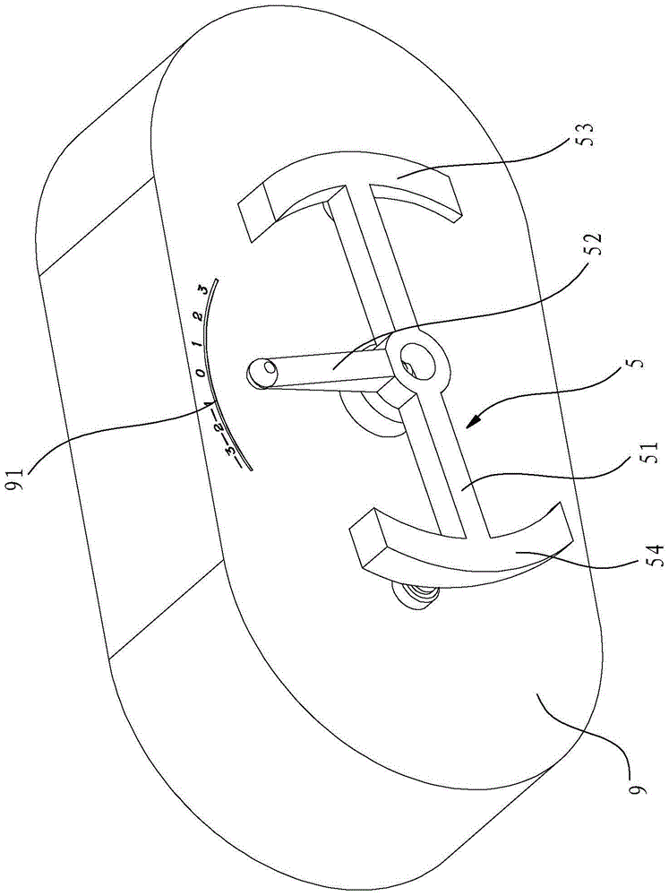
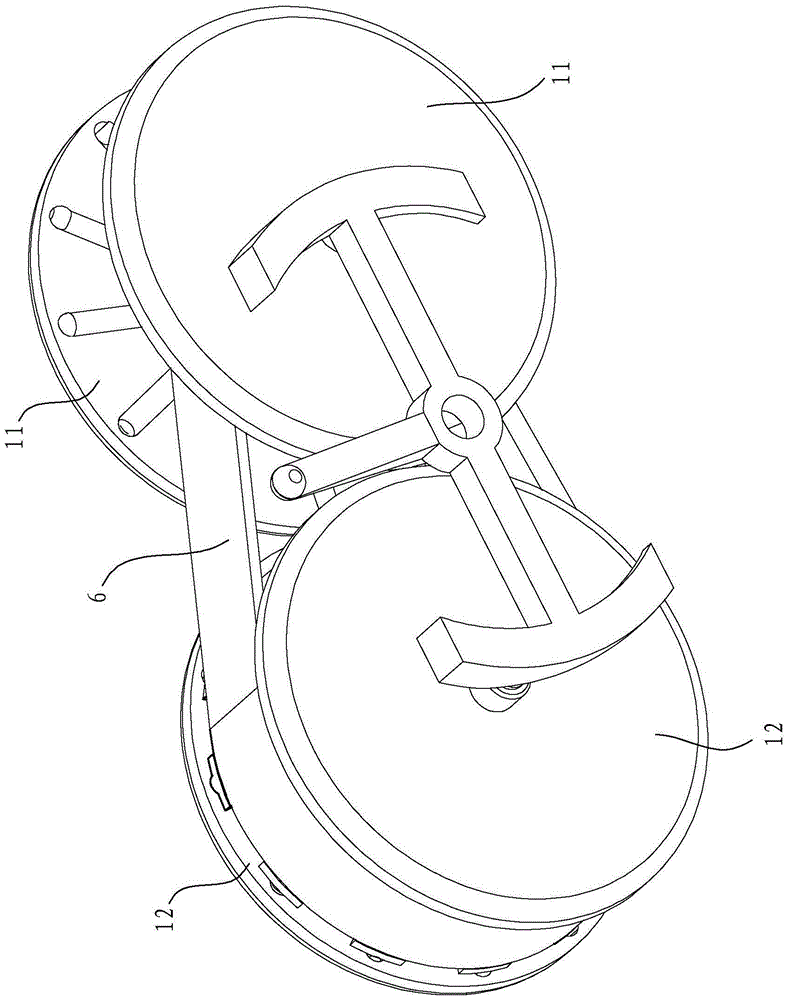
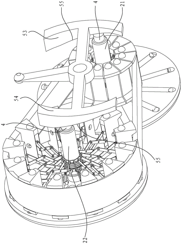
[0047] Such as Figure 1 to Figure 8 As shown, the continuously variable transmission in this embodiment includes a housing 9, a driving disc 11, a driven disc 12, a first mounting shaft 21, a second mounting shaft 22, a first slider group 31, and a second slider group 32 , the first connecting piece, the second connecting piece, the pin shaft 4, the trigger link 5, the transmission belt 6, the spring 7 and other main components. The driving disc 11 and the driven disc 12 are all located in the housing 9, the driving disc 11 is adjacent to the driven disc 12, the first mounting shaft 21 is the driving shaft and is installed in the center of the driving disc 11, and the second mounting shaft 22 is connected to the driving disc 11. The drive shaft is also installed in the center of the driven disk 12 , the first installation shaft 21 and the se...


PUM


Abstract

A stepless transmission comprises a driving disc, a driven disc, a first installation shaft, a second installation shaft, a first sliding block set, a second sliding block set, a first axial force application component, a second axial force application component, a triggering connecting rod, a first elastic piece, a second elastic piece and a transmission belt. When the first axial force application component and the second axial force application component axially move in the opposite directions, the first sliding block set and the second sliding block set radially move oppositely, the transmission belt is driven to move, uniform and continuous changes are formed through the radius of a rotating disc composed of the first sliding block set and the second sliding block set so as to generate different radius ratios, and therefore stepless transmission is formed. The stepless transmission is simple in structure, small and exquisite in size and stable and reliable in working. The invention further discloses a bicycle applying the stepless transmission. A gear shifting device of the bicycle is high in sensitivity, stepless transmission can be easily carried out, the best transmission speed ratio can be kept all the time in the riding process, and the phenomena of gear shifting delay and power transmission power-off are avoided.

Description

technical field [0001] The invention relates to a speed changer and a bicycle equipped with the speed changer, in particular to a continuously variable speed changer and a bicycle equipped with the speed changer. Background technique [0002] Most of the existing mechanical transmission devices adopt gear shifting, that is, pole shifting. The disadvantages of gear shifting mainly lie in: not only the operation is relatively complicated, the use is relatively inconvenient, but also the operation is not stable when shifting. In order to overcome the defects of the existing gear shifting structure, people have invented various continuously variable transmissions with different structures at present, such as the Chinese invention patent disclosed by the patent No. ZL201010184634. Belt drive type continuously variable transmission mechanism", the continuously variable transmission mechanism has several curved surfaces in the form of wave-shaped concave and convex that divide the ...

Claims


Application Information

Patent Timeline
Patent Type & Authority Patents(China)
IPC IPC(8): B62M9/08B62M9/06
CPCB62M9/06B62M9/08
Inventor 吕元胜
Owner 吕元胜
Why Eureka
Try Eureka