Electrical connector that dampens electrical resonance

a technology of electrical resonance and electrical connector, which is applied in the direction of coupling contact members, coupling device connections, coupling protective earth/shielding arrangements, etc., can solve the problems of electrical performance inhibition of known electrical connectors and electrical problems of electrical connectors, and achieve the effect of dissipating electrical energy and dissipating electrical energy

Active Publication Date: 2018-08-14
TYCO ELECTRONICS (SHANGHAI) CO LTD +1
View PDF9 Cites 4 Cited by
  • Summary
  • Abstract
  • Description
  • Claims
  • Application Information

AI Technical Summary

Benefits of technology

[0006]In an embodiment, an electrical connector is provided that includes a housing, signal conductors, and ground conductors. The signal conductors and ground conductors are held by the housing. The ground conductors are arranged in an array with the signal conductors and provide electrical shielding between the signal conductors. The ground conductors have an electrically conductive metal body extending a length between a terminating end and a mating distal end. The ground conductors are configured to engage corresponding mating ground conductors of a mating connector at a contact location of the respective ground conductor. The ground conductors further include a damping segment disposed between the contact location and the mating distal end. The damping segment is characterized by a lossy coating at least partially covering the metal body to dissipate electrical energy.
[0007]In another embodiment, an electrical connector is provided that includes a housing, signal conductors, and ground conductors. The signal conductors and ground conductors are held by the housing. The ground conductors are arranged in an array with the signal conductors. The ground conductors have an electrically conductive metal body extending a length between a terminating end and a mating distal end. The metal body includes a center wall and at least one side wall extending from the center wall to surround and electrically shield at least one of the signal conductors on at least two sides thereof. The ground conductors are configured to engage corresponding mating ground conductors of a mating connector at a contact location of the respective ground conductor. The ground conductors further includes a damping segment disposed along the center wall and the at least one side wall between the contact location and the mating distal end of the ground conductor. The damping segment is characterized by a lossy coating at least partially covering the metal body to dissipate electrical energy.

Problems solved by technology

Some known electrical connectors have electrical problems, particularly when transmitting at high data rates.
However, electrical performance of known electrical connectors is inhibited by resonance spikes at certain frequencies when transmitting high speed electrical signals, even with the presence of ground conductors disposed between the signal conductors.

Method used


Image

  • Electrical connector that dampens electrical resonance
  • Electrical connector that dampens electrical resonance
  • Electrical connector that dampens electrical resonance

Examples


Embodiment Construction

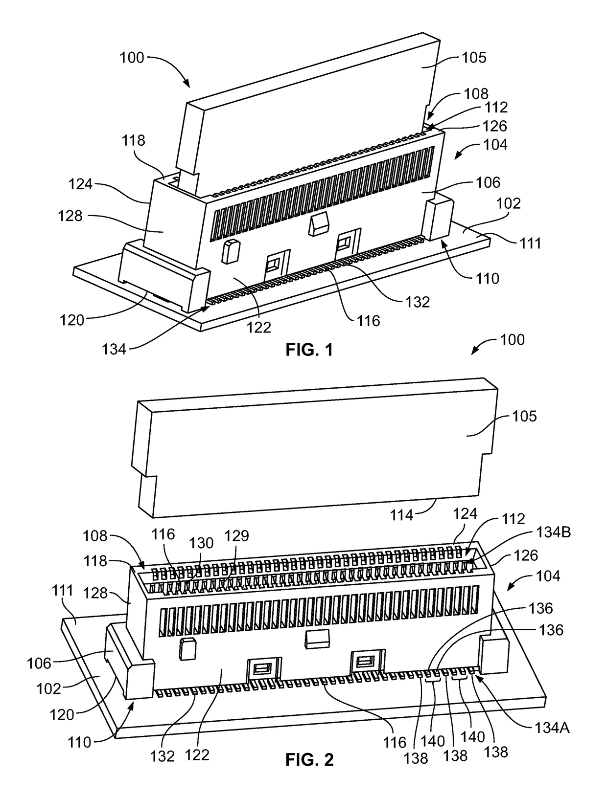
[0015]FIG. 1 is a top perspective view of an electrical connector system 100 according to an embodiment showing components in a mated state. FIG. 2 is a top perspective view of the electrical connector system 100 showing components in an unmated state. The electrical connector system 100 includes a circuit board 102 and a first electrical connector 104 mounted to the circuit board 102. The first electrical connector 104 is configured to electrically connect to a second electrical connector 105 (also referred to as mating connector 105) in order to provide an electrically conductive signal path between the circuit board 102 and the mating connector 105. The first electrical connector 104 may be a high speed connector that transmits data signals at speeds over 10 gigabits per second (Gbps), such as over 25 Gbps or over 35 Gbps. The electrical connector 104 may also be configured to transmit low speed data signals and / or power. The electrical connector 104 optionally may be an input-ou...


PUM


Abstract

An electrical connector includes a housing and both signal conductors and ground conductors held by the housing. The ground conductors are arranged in an array with the signal conductors and provide electrical shielding between the signal conductors. The ground conductors have an electrically conductive metal body extending a length between a terminating end and a mating distal end. The ground conductors are configured to engage corresponding mating ground conductors of a mating connector at a contact location of the respective ground conductor. The ground conductors further include a damping segment disposed between the contact location and the mating distal end. The damping segment is characterized by a lossy coating at least partially covering the metal body to dissipate electrical energy.

Description

CROSS-REFERENCE TO RELATED APPLICATIONS[0001]This application claims priority to Chinese Patent Application No. 201710075844.6, filed on 13 Feb. 2017, which is incorporated by reference herein in its entirety.BACKGROUND OF THE INVENTION[0002]The subject matter herein relates generally to electrical connectors that provide electrical damping by dissipating electrical energy from conductors of the connectors.[0003]Some electrical connector systems utilize electrical connectors, such as board-mounted connectors, cable-mounted connectors, or the like, to interconnect two circuit boards, such as a motherboard and daughter card. The conductors of a first electrical connector are terminated to one circuit board and extend through a housing of the first electrical connector towards a mating end to engage mating conductors of a second connector that is terminated to the other circuit board.[0004]Some known electrical connectors have electrical problems, particularly when transmitting at high...

Claims


Application Information

Patent Timeline
Patent Type & Authority Patents(United States)
IPC IPC(8): H01R13/648H01R13/6473H01R13/6471H01R12/72H01R12/70
CPCH01R13/6473H01R13/6471H01R12/721H01R12/7082H01R12/716H01R13/02H01R13/03H01R13/652H01R12/737
Inventor PICKEL, JUSTIN DENNISMORGAN, CHAD WILLIAMMUNOZ, ARTURO PACHONORRIS, DAVID PATRICKHUANG, LIANG
Owner TYCO ELECTRONICS (SHANGHAI) CO LTD
Why Eureka
Try Eureka