Dielectric fittings

Inactive Publication Date: 2006-05-11
PARKER HANNIFIN CORP
View PDF16 Cites 81 Cited by
  • Summary
  • Abstract
  • Description
  • Claims
  • Application Information

AI Technical Summary

Benefits of technology

[0011] Accordingly, in order to overcome the deficiencies of the prior art devices, the present invention provides a number of embodiments of dielectric tubular fittings for not only dissipating the electrical energy from s

Problems solved by technology

Again, the noted structure does not have any controlled resistance or capability to retain high pressure fluid.
In the event of a lightning strike, this non-controlled electrical resistance means that the full power of the lightning strike can pass through the line and into the fuel/air mixtures that may be found inside of an aircraft fuel tank.
These minimum isolating area

Method used


Image

  • Dielectric fittings
  • Dielectric fittings
  • Dielectric fittings

Examples


Embodiment Construction

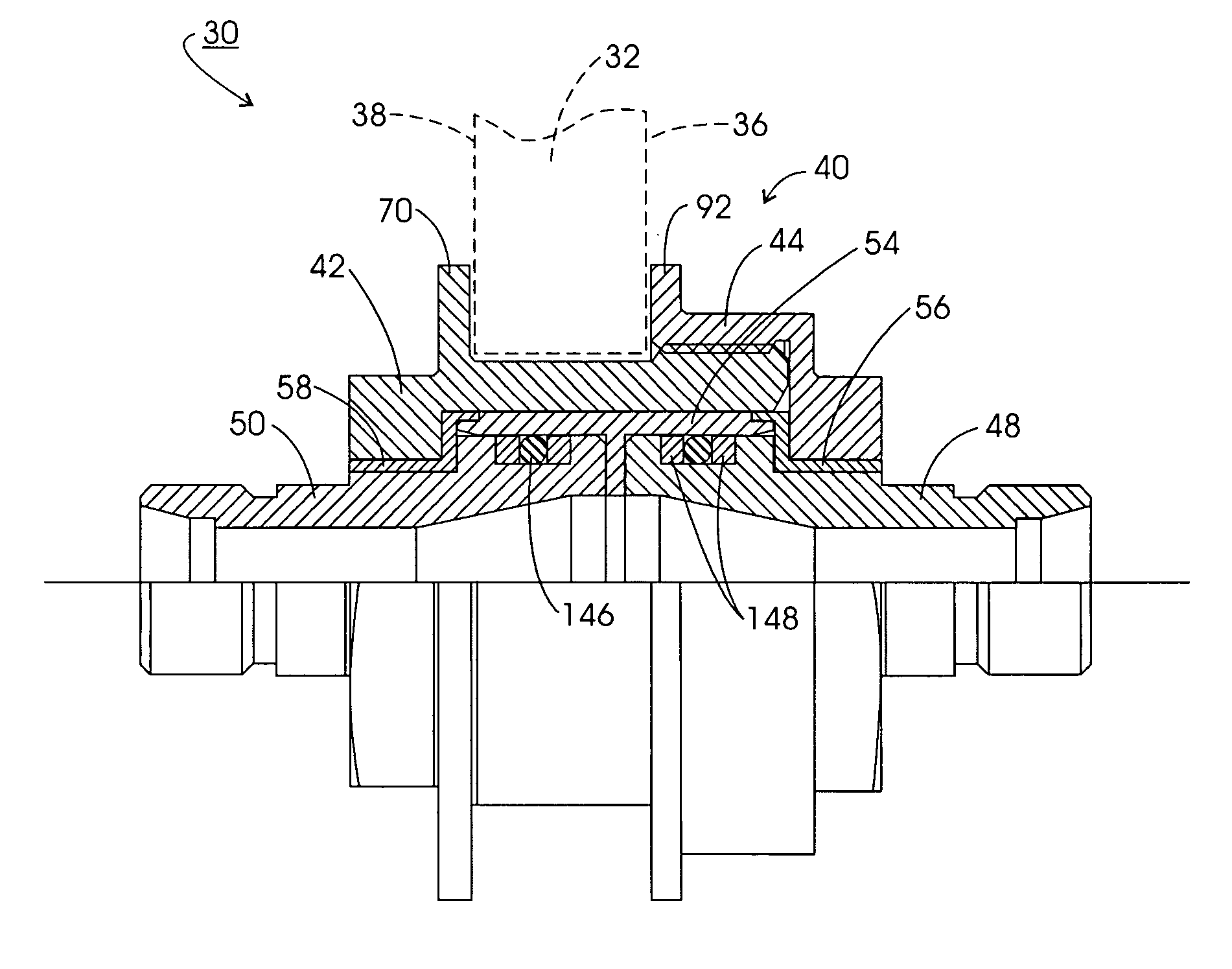
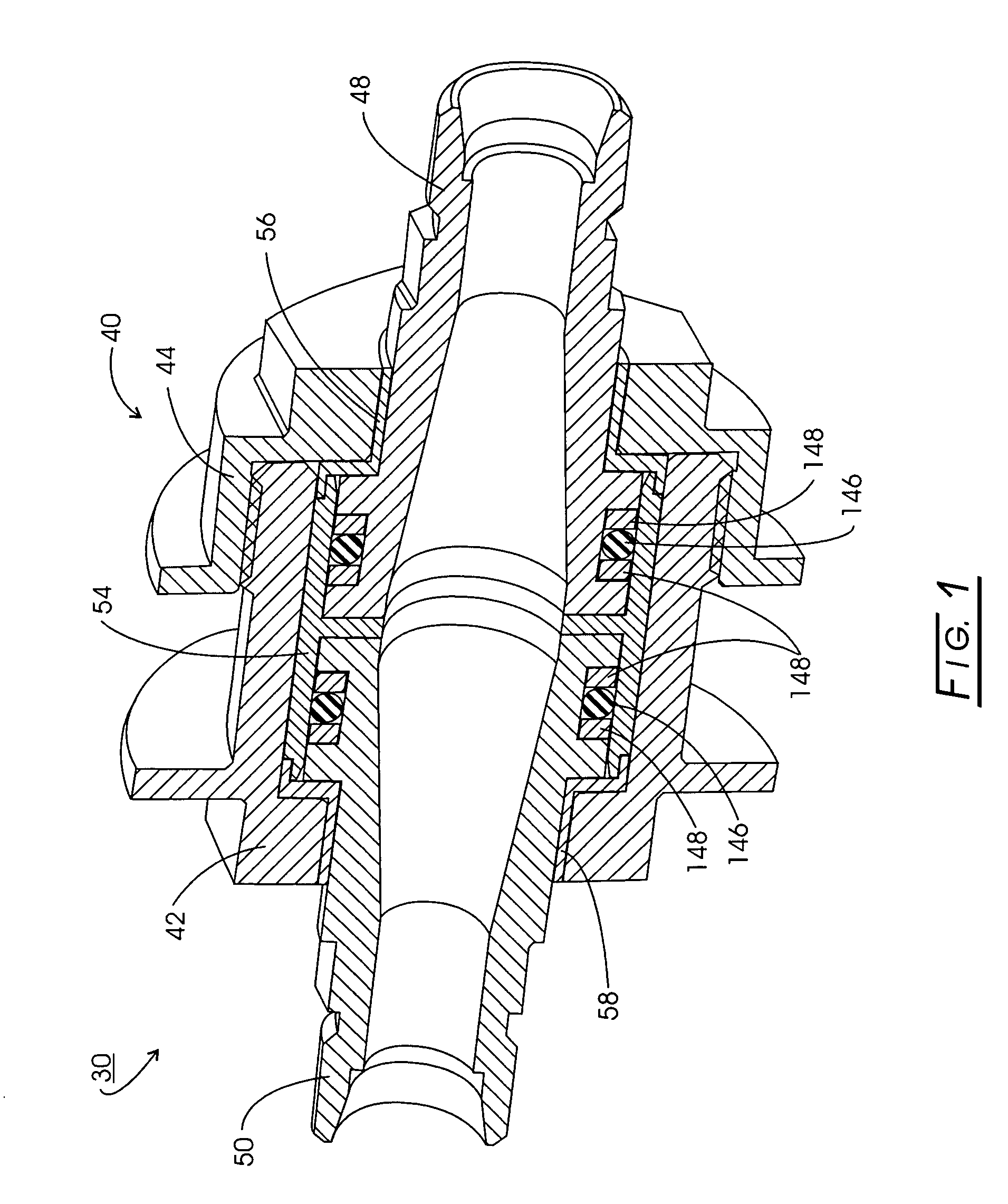
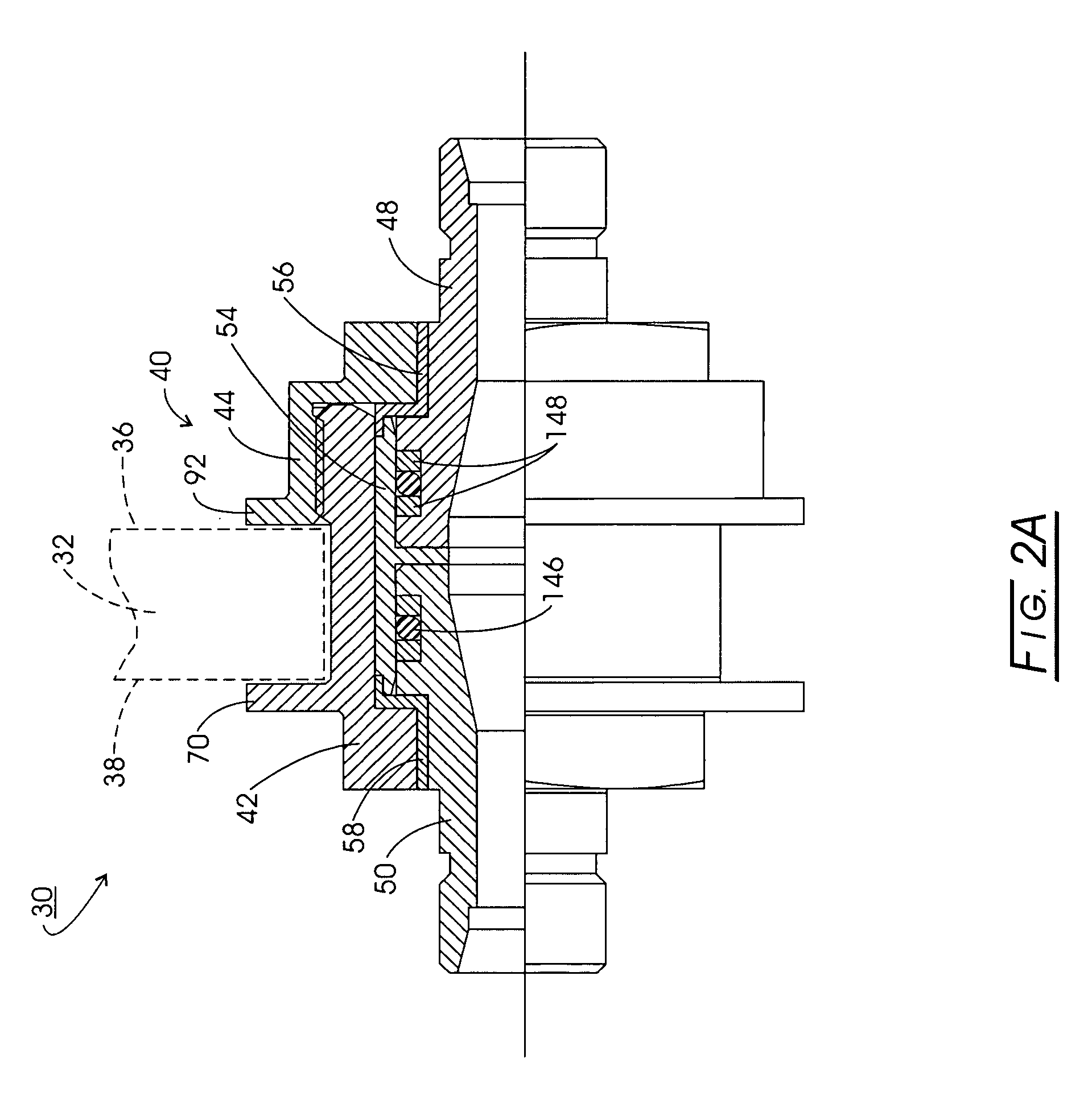
[0080] Referring now to the multiple drawings, illustrated in FIGS. 1-12 is a first embodiment 30 and a variation 30′ of one of the several dielectric fittings of this invention. Dielectric fitting 30 is defined as a bulkhead-type fitting since it is designed to extend through a bulkhead 32 (FIG. 2) of a vessel, such as an aircraft, with bulkhead 32 including an air side or outer side 36 and a fuel side or inner side 38. It should be understood that dielectric fittings, such as fitting 30, can be used in a many other applications, such as gas to gas, liquid to liquid, gas / liquid to gas / liquid, or the like. Fitting 30, as best seen in FIGS. 1 and 2A, basically includes a housing 40, comprised of bulkhead bolt or inner housing 42 and bulkhead nut or outer housing 44; a pair of oppositely-directed, generally tubular and substantially similar adapters 48 and 50; a center dielectric insulator 54; and a pair of oppositely-directed, generally tubular and substantially similar end dielectri...


PUM


Abstract

A dielectric tubular fitting for dissipating electrical energy, while providing fluid flow therethrough, the fitting including coaxial first and second generally tubular light metal housings, with a first, generally cylindrical, spacer of a Peek material composition being sealingly interposed therebetween and a first generally disc-shaped first ESD (Electrostatic Discharge) spacer, of a Krefine material composition, for controlling the electrical resistance between the first and second housings, being additionally interposed between as well as both axially and radially separating at least the first and second housings, with a tubular insulator housing, of a carbon filled PTFE type material composition, enveloping at least a portion of the first housing. Several embodiments of both in-line and bulkhead type fittings are set forth, one of the latter including frangible screws and an external fracture plane, with an internal controlled weak portion including an internal fracture plane, these fracture planes providing controlled breakaway features.

Description

CROSS-REFERENCE TO RELATED CASES [0001] The present application claims the benefit of the filing dates of U.S. Provisional Patent Application Ser. No. 60 / 624,109, filed Nov. 1, 2004 and U.S. Provisional Application Ser. No. 60 / 672,818, filed Apr. 19, 2005, the disclosures of which are incorporated herein by reference.FIELD OF THE INVENTION [0002] The present invention pertains to tubular dielectric fittings for use in applications such as gas to gas, liquid to liquid, gas / liquid to gas / liquid and the like. These dielectric fittings include bulkhead types that are designed to extend through the bulkhead of a vessel, such as an aircraft, and also include in-line types that permit high pressure fluid to travel from side to side. BACKGROUND OF THE INVENTION [0003] Dielectric fittings are known in the art and have found use in many applications, ranging from natural gas pipelines, where they isolate monitoring instruments from the effects of electrical current and interrupt cathodic curr...

Claims


Application Information

Patent Timeline
IPC IPC(8): H01R13/52
CPCF16L25/02F16L25/023H01R13/6485F16L5/12B64D37/005B64D37/32B64D45/02
Inventor FULLNER, TODD C.ZHANG, GEOFFREYMARBAN, JOSEPH
Owner PARKER HANNIFIN CORP
Why Eureka
Try Eureka