Charging Circuit and Method for Operating Such Circuit

a charging circuit and circuit technology, applied in the field of power electronics, can solve the problems of limited number of pre-charge attempts, high current, and high cost of components, and achieve the effect of optimizing the circuit operation

Active Publication Date: 2013-03-14
V2 PLUG IN HYBRID VEHICLE PARTNERSHIP HANDELSBOLAG
View PDF7 Cites 7 Cited by
  • Summary
  • Abstract
  • Description
  • Claims
  • Application Information

AI Technical Summary

Benefits of technology

[0004]The invention provides in a first aspect a Charging circuit comprising: a first input terminal and a second input terminal for connecting the circuit to a first supply terminal and a second supply terminal, respectively, of a DC power source; a first output terminal and a second output terminal for providing an output voltage to a load to be charged; a first switch arranged between the first input terminal and the first output terminal; a current sensor arranged between the first input terminal and the first output terminal in series with the first switch; a connecting element comprising a first inductance connector and a second inductance connector for connecting an inductance, the first inductance connector connected to the switch and the second connector connected to the second output terminal; a diode element connected to the first inductance connector and the second output terminal such that when the first switch is switched on, current flowing through the switch is prevent from flowing from the switch to the second output terminal via the diode element; the first switch and the current sensor being arranged to be connected to a control circuit arranged for controlling operation of the switch in response to a signal received from the current sensor.
[0005]By enabling the use of an inductance rather than a resistor for limiting the current in the circuit, the current is limited in a way that electrical energy is preserved in the circuit, rather than dissipated. The diode element is provided to enable energy stored in the inductance to flow to the load when the switch is switched off. Furthermore, by operating the switch in relation to the current sensed, the switch can be operated to enable optimally efficient operation of the circuit.

Problems solved by technology

At the moment such load is connected to a power supply, this can result in high currents, in particular if the power supply has a low internal resistance.
These components are expensive and bulky.
Furthermore only a limited number of pre-charge attempts can be made in a limited time frame before the resistor will overheat.

Method used


Image

  • Charging Circuit and Method for Operating Such Circuit
  • Charging Circuit and Method for Operating Such Circuit
  • Charging Circuit and Method for Operating Such Circuit

Examples


Embodiment Construction

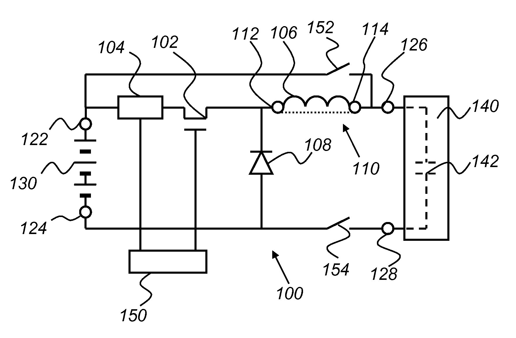
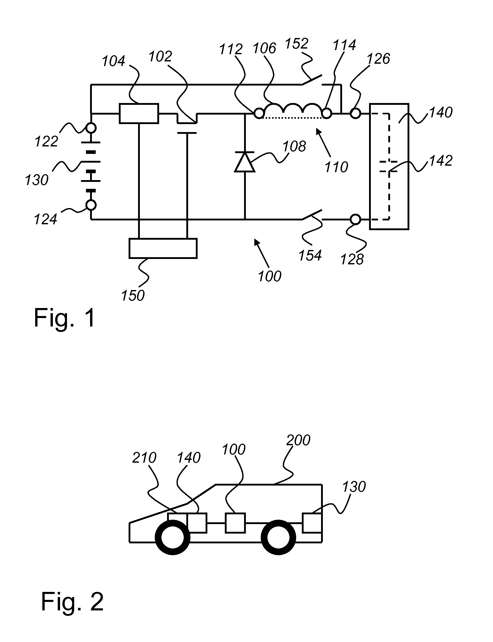
[0025]FIG. 1 discloses a circuit 100 as an embodiment of the charging circuit according to the invention. The circuit 100 comprises a MOSFET 102 as a first switch, a current sensor 104, connected in series with the MOSFET 102 for sensing the current through the MOSFET 102, an inductor connecting element 110 comprising a first inductor connector 112 connected to the MOSFET 102 and a second inductor connector 114. An inductor 106 as an inductive element is connected in series with the MOSFET 102 and the current sensor 104 via the inductor connecting element 110.

[0026]The circuit 100 further comprises a first input terminal 122 and a second input terminal 124 that are both arranged to connect the circuit 100 to a battery 130 as a DC power source. A person skilled in the art will appreciate that also other DC power sources may be connected to the circuit 100, like a rectifier circuit connected to an AC power source. The circuit 100 also comprises a first output terminal 126 and a second...


PUM


Abstract

A charging circuit includes first and second input terminals connecting the circuit to first and second supply terminals, respectively, of a DC power source, first and second output terminals providing an output voltage to a load to be charged, a first switch between the first and second input terminals, a current sensor between the first input terminal and the first output terminal in series with the first switch, a connecting element having first and second inductance connectors for connecting an inductance, the first inductance connector connected to the switch and the second inductance connector connected to the first output terminal, and a diode element connected to the first inductance connector and the second output terminal. The first switch and the current sensor are arranged to be connected to a control circuit arranged for controlling operation of the first switch in response to a signal received from the current sensor.

Description

TECHNICAL FIELD[0001]The invention relates to the field of power electronics and in particular to the field of charging a load.BACKGROUND OF THE INVENTION[0002]Various loads to be powered by an electrical power supply comprise capacitances. These capacitances may be either parasitic or intended capacitances. At the moment such load is connected to a power supply, this can result in high currents, in particular if the power supply has a low internal resistance. This may for example be the case with a battery. A possible solution for this is by switched charging. A battery is connected to a load comprising a certain capacitance via a relay and a resistor. These components are expensive and bulky. Furthermore they need to be matched to the system load in order to fulfil required pre-charge time. This makes the circuit sensitive to variations (ex. age and temperature) or changes and modifications to the system. Furthermore only a limited number of pre-charge attempts can be made in a li...

Claims


Application Information

Patent Timeline
Patent Type & Authority Applications(United States)
IPC IPC(8): H02J7/00
CPCH02J7/0065B60L2240/547B60L2240/80Y02T90/14Y02T10/7072B60L53/22H02J2207/20Y02T10/70H02J7/0049Y02T90/12
Inventor MARTAENG, JESPER
Owner V2 PLUG IN HYBRID VEHICLE PARTNERSHIP HANDELSBOLAG
Why Eureka
Try Eureka