Implant having adjustable filament coils

a technology of filament coils and filament coils, which is applied in the field of securing soft tissue to bone, can solve the problems of graft movement away from the desired location, loosening or sliding of the graft, and limitations of existing devices and methods

Active Publication Date: 2018-08-21
MEDOS INT SARL
View PDF303 Cites 6 Cited by
  • Summary
  • Abstract
  • Description
  • Claims
  • Application Information

AI Technical Summary

Benefits of technology

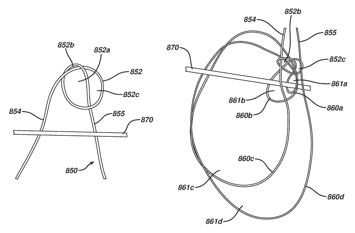
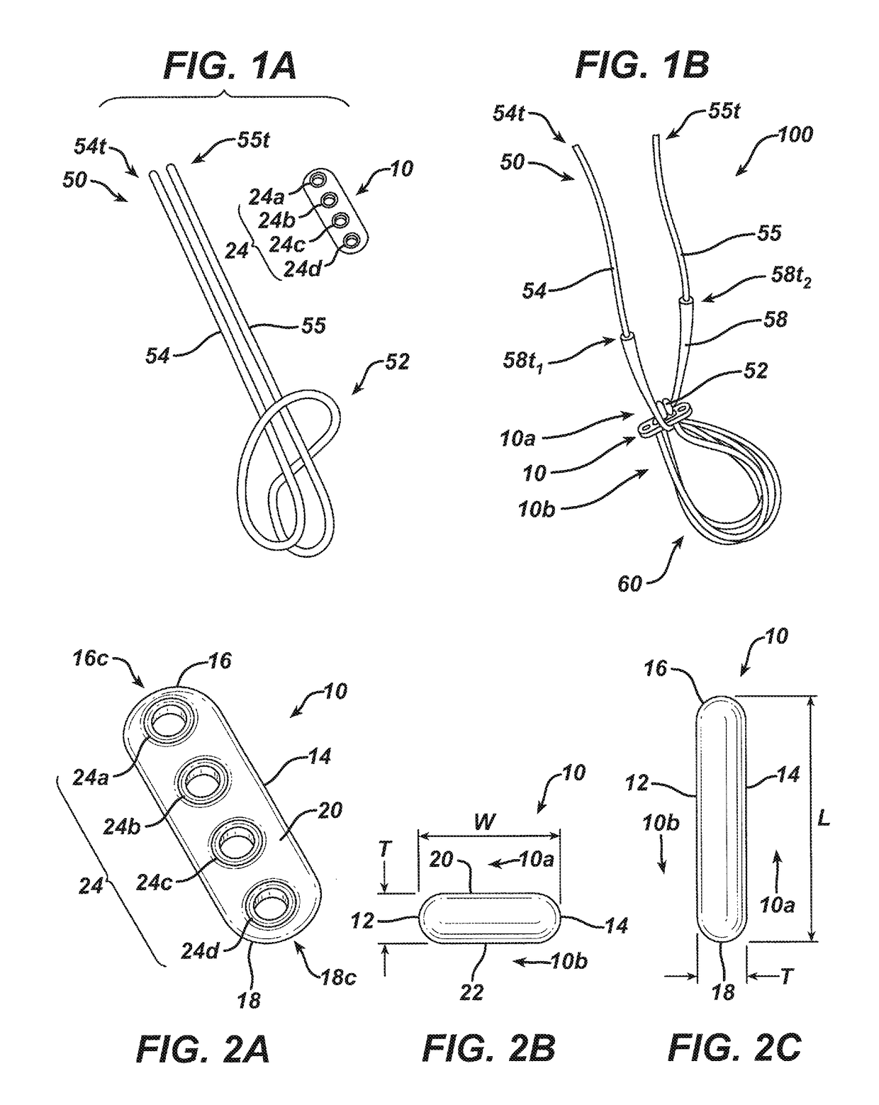
[0013]In some embodiments, additional loops can be formed from the suture filament. For example, the suture filament can be arranged with respect to the body such that its first portion passes through one thru-hole to the bottom side of the body and through a different thru-hole to the top side to form a third loop, while its second portion passes through one thru-hole to the bottom side of the body and through a different thru-hole to the top side to form a fourth loop. In some embodiments the thru-holes of the body include two outer thru-holes and two inner thru-holes, with each outer thru-hole being located on an outer portion of the body and the inner thru-holes being disposed between the outer thru-holes. In such embodiments, the first and second portions of the suture filament can pass through each of the outer thru-holes and through each of the inner thru-holes at least once. Alternatively, in such embodiments, the first and second portions of the suture filament can pass through each of the inner thru-holes at least twice. A length of the filament's first portion and a length of the filament's second portion can be adjustable. In some embodiments the implant can include a second suture filament extending longitudinally through the body. The second suture filament can pass through each thru-hole of the plurality of thru-holes, and can be used, for example, as a shuttle to help guide the implant through a bone tunnel.
[0014]One exemplary embodiment of a surgical method includes loading a graft onto one or more coils of a plurality of coils of an implant filament that is coupled to an implant body, pulling a leading end of a shuttle filament that is disposed through the implant body through a bone tunnel until the implant body is pulled out of the tunnel while at least a portion of the implant filament and the graft remain in the tunnel, and orienting the implant body so that its bottom side is facing the bone tunnel through which the implant body passed. Pulling the leading end of the shuttle filament also necessarily pulls the implant body, the implant filament, and the graft through the tunnel. The resulting orientation of the implant's bottom side facing the tunnel is such that the plurality of coils are disposed substantially within the tunnel and a sliding knot first and second terminal ends of the implant filament are located outside of the tunnel, adjacent to a top side of the implant body.
[0015]In some embodiments, the step of orienting the implant body can be performed by pulling a trailing end of the shuttle filament. Alternatively, the step of orienting the implant body can be performed by pulling both the leading and trailing ends of the shuttle filament. The method can further include selectively applying tension to at least one of the first and second terminal ends to adjust a circumference of one or more of the coils.

Problems solved by technology

Existing devices and methods can be limited because they do not always provide the desired strength.
In some instances, one or more knots tied to help maintain a location of the suture loop with respect to a cortical button, and thus the graft associated therewith, can loosen or slip.
Thus, even if a ligament graft is disposed at a desired location during a procedure, post-operatively the circumference of the loop can increase, causing the graft to move away from the desired location.
Further, it can be desirable to limit the number of knots used in conjunction with such devices, because of the potential for the knots loosening and because the additional surface area knots can increase the risk of trauma.
Some existing knot configurations used in conjunction with procedures of this nature can undesirably bind, which can prevent the knot from cinching down and leads to the knot having a higher profile.
Still further, existing devices and methods also lack adjustability in many instances.
For example, in procedures in which multiple ligament grafts are associated with the cortical button, it can be difficult to control placement of one ligament graft independently (i.e. without also moving the other ligament graft).

Method used


Image

  • Implant having adjustable filament coils
  • Implant having adjustable filament coils
  • Implant having adjustable filament coils

Examples


Embodiment Construction

[0055]Certain exemplary embodiments will now be described to provide an overall understanding of the principles of the structure, function, manufacture, and use of the devices and methods disclosed herein. One or more examples of these embodiments are illustrated in the accompanying drawings. Those skilled in the art will understand that the devices and methods specifically described herein and illustrated in the accompanying drawings are non-limiting exemplary embodiments and that the scope of the present invention is defined solely by the claims. The features illustrated or described in connection with one exemplary embodiment may be combined with the features of other embodiments. Such modifications and variations are intended to be included within the scope of the present invention. Further, in the present disclosure, like-numbered components of the embodiments generally have similar features. Additionally, to the extent that linear or circular dimensions are used in the descrip...


PUM


Abstract

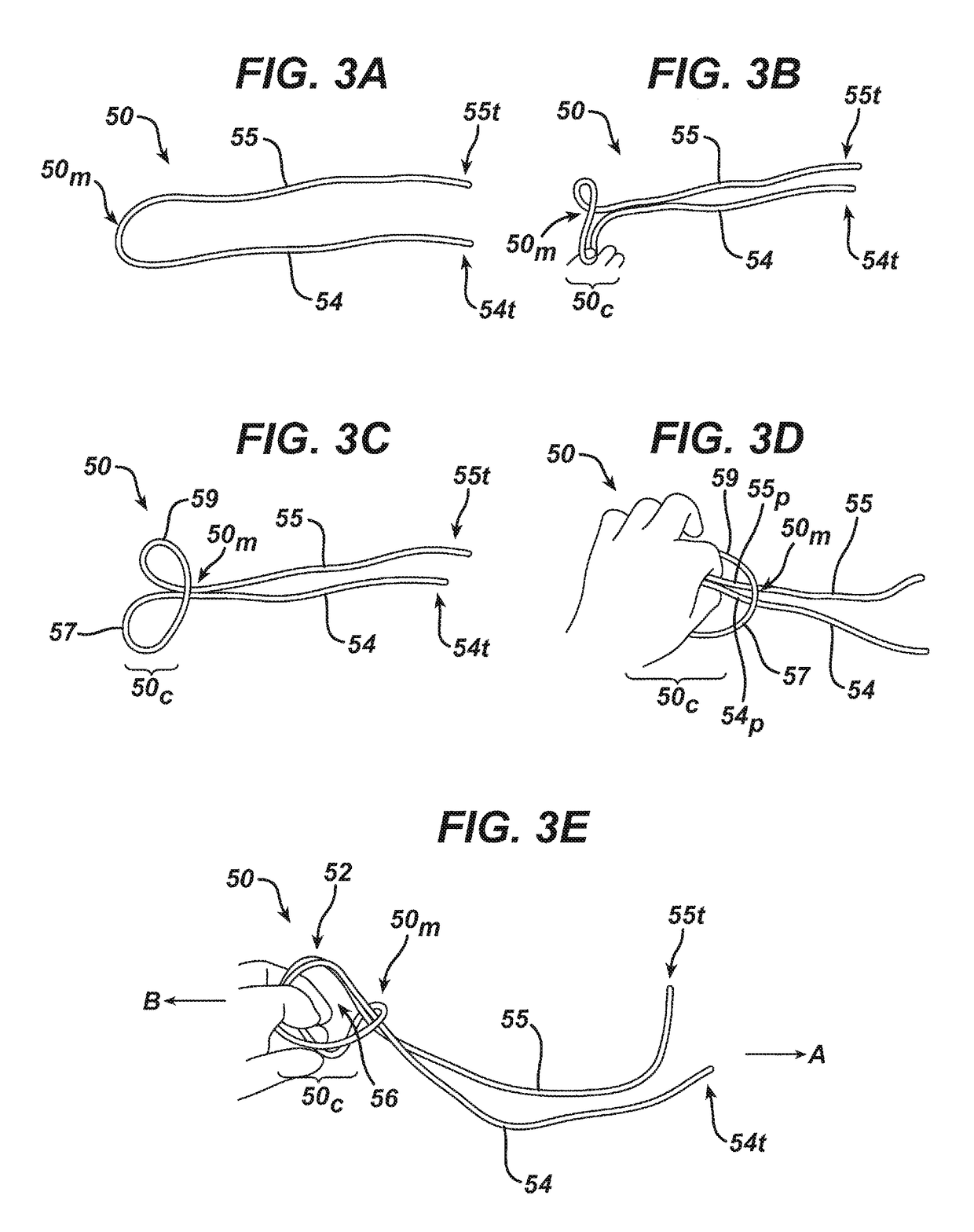
Devices and methods for soft tissue reconstruction are provided. One exemplary embodiment of a device includes a body a suture filament extending through through-holes formed in the body. The suture is formed into an overhand knot having three collapsible openings with filament limbs extending from the knot. The limbs can be passed through the thru-holes of the body and selectively into the collapsible openings of the overhand knot to form coils extending to an opposite side of the body. For example, one limb can be passed through first and second collapsible openings to form two coils, while the other limb can be passed through the first and third collapsible openings to form two coils. The collapsible openings are collapsed around the limbs disposed in the openings, resulting in a secured overhand knot. Other configurations of knots, as well as devices and methods for use in tissue reconstruction, are also provided.

Description

CROSS REFERENCE TO RELATED APPLICATIONS[0001]The present application is a continuation-in-part of and claims priority to U.S. patent application Ser. No. 13 / 793,514, filed on Mar. 11, 2013, and entitled “Implant Having Adjustable Filament Coils,” which is hereby incorporated by reference in its entirety.FIELD[0002]The present disclosure relates to devices, systems, and methods for securing soft tissue to bone, and more particularly it relates to securing an ACL graft to a femur.BACKGROUND[0003]Joint injuries may commonly result in the complete or partial detachment of ligaments, tendons, and soft tissues from bone. Tissue detachment may occur in many ways, e.g., as the result of an accident such as a fall, overexertion during a work related activity, during the course of an athletic event, or in any one of many other situations and / or activities. These types of injuries are generally the result of excess stress or extraordinary forces being placed upon the tissues.[0004]In the case ...

Claims


Application Information

Patent Timeline
Patent Type & Authority Patents(United States)
IPC IPC(8): A61B17/04A61F2/08A61B17/06
CPCA61B17/0401A61F2/0811A61F2002/0882A61B2017/0404A61F2002/0852A61B2017/0475A61B2017/06185A61F2002/0829A61B2017/0458
Inventor SPENCINER, DAVID B.
Owner MEDOS INT SARL
Why Eureka
Try Eureka