Detachable LED lighting device

a technology of led lighting and led brackets, which is applied in the direction of fixed installation, lighting and heating equipment, lighting support devices, etc., can solve the problems of difficult disassembly and one worker's time-consuming and labor-intensive problems, and achieve the effect of reducing time and cost, easy separation, and easy coupling and disassembly

Inactive Publication Date: 2018-08-28
GIGATERA INC
View PDF12 Cites 2 Cited by
  • Summary
  • Abstract
  • Description
  • Claims
  • Application Information

AI Technical Summary

Benefits of technology

[0009]In order to address the problems above, the present invention provides a detachable LED lighting device by which one worker can easily perform the replacement of the lighting module for each unit.
[0010]In addition, the present invention provides a detachable LED lighting device in which the number of lighting modules can be easily changed in order to immediately meet the user's request.
[0012]The detachable LED lighting device of the present invention may include: a frame unit that has a power supply unit embedded therein; and a lighting module unit that is fitted and fixed to the frame unit at both ends thereof, and that is easily separated from the frame unit by manipulation of a pressing button that is exposed to the both ends so that the lighting module unit can be more easily coupled and detached, thereby reducing the time and cost required for maintenance.
[0013]In addition, the detachable LED lighting device of the present invention may easily change the number of lighting module units, which are mounted on the frame unit, according to the illuminance requested by the user in order to thereby enhance the user's convenience and in order to thereby provide versatility by which the lighting device of the same design can be applied for various uses.

Problems solved by technology

In such a configuration, in order to replace one lamp housing, all or some of the brackets are required to be disassembled, which takes a long time.
In particular, since the lamp housing is heavy, it is very hard for one worker to perform the disassembly, considering that the streetlight requires a high place work.

Method used


Image

  • Detachable LED lighting device
  • Detachable LED lighting device
  • Detachable LED lighting device

Examples


Embodiment Construction

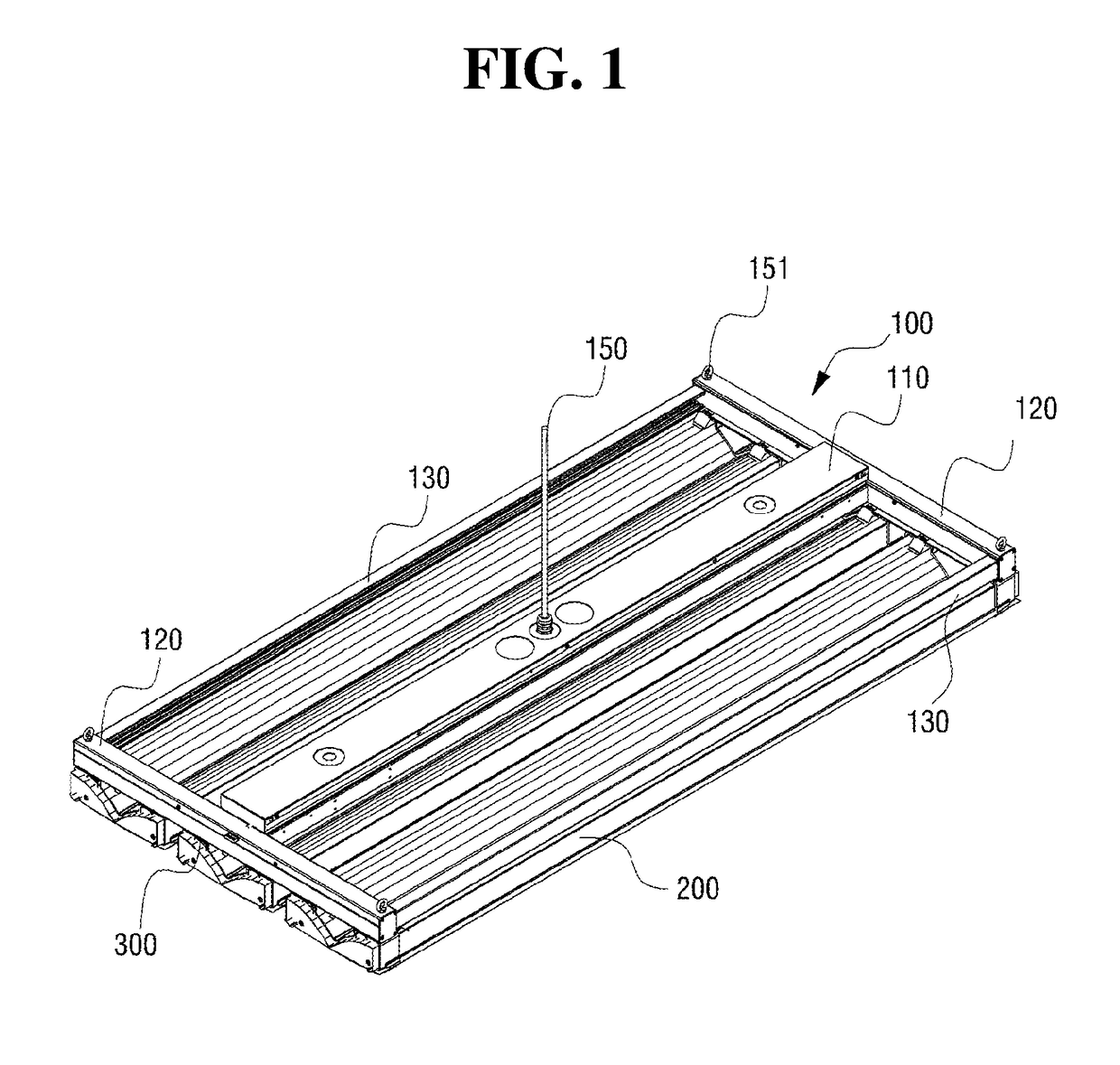
[0026]Hereinafter, a detachable LED lighting device of the present invention will be described in detail with reference to the accompanying drawings. FIG. 1 is a perspective view showing the assembled state of a detachable

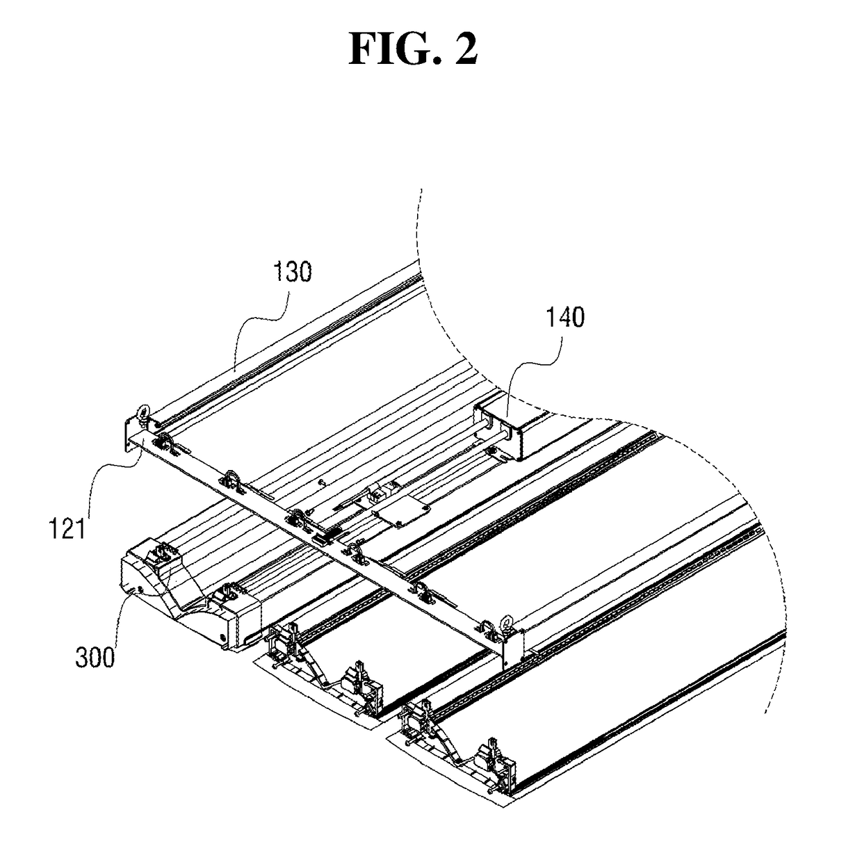
[0027]LED lighting device, according to a preferred embodiment of the present invention, and FIG. 2 is a partially exploded perspective view of FIG. 1.

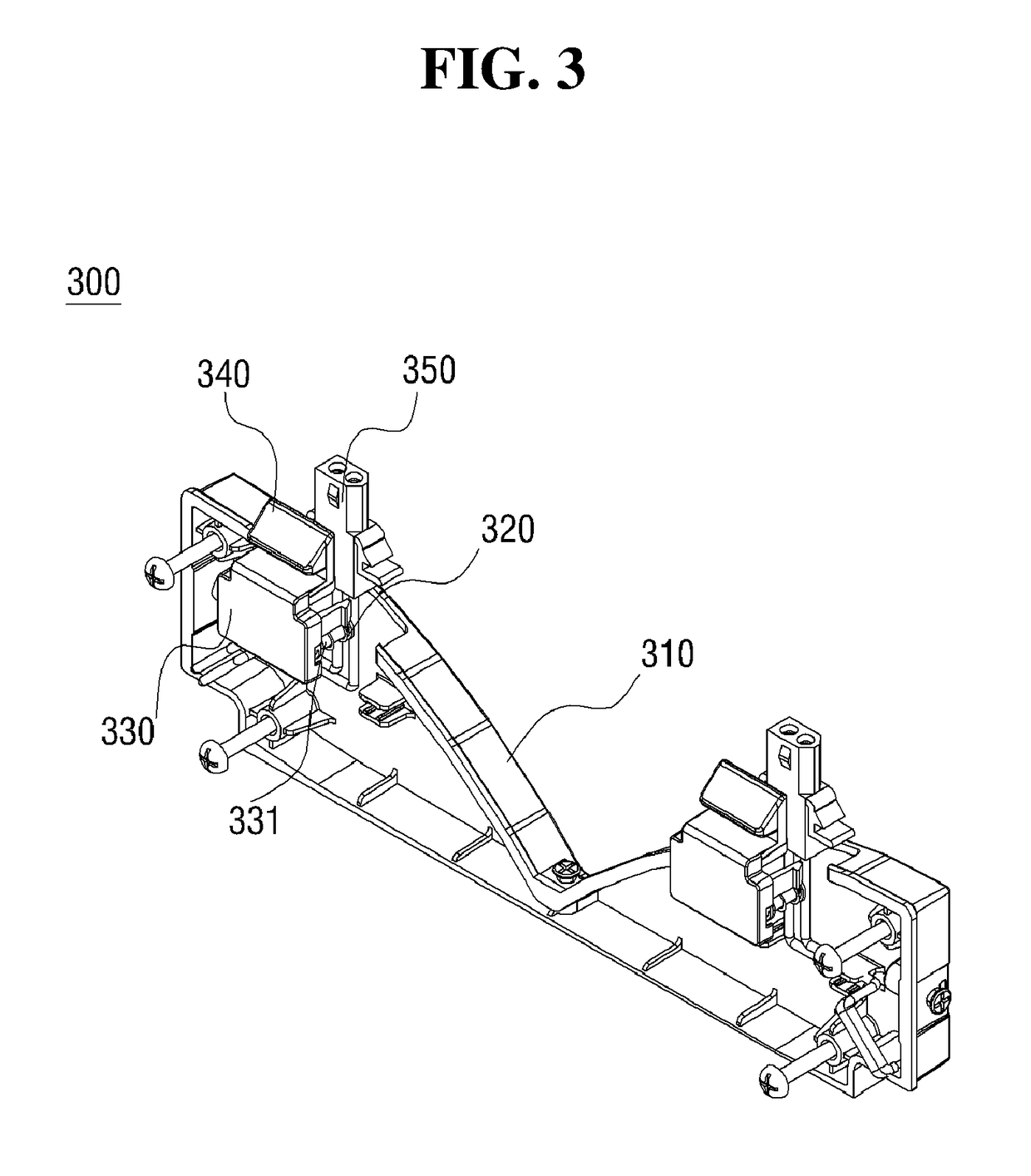
[0028]Referring to FIGS. 1 and 2, the detachable LED lighting device, according to a preferred embodiment of the present invention, is configured to include: a frame unit 100 that has a power supply unit 140 mounted therein, and that provides a plurality of power connectors 124 for supplying power of the power supply unit 140; and a connector unit 300 that is coupled to both ends of a lighting module unit 200, and that fixes both ends of the lighting module unit 200 to the bottom surface of the frame unit 100 by a tight fit while being connect to the power connector 124 in order to thereby supply power to the lightin...


PUM


Abstract

The present invention relates to a detachable LED lighting device, comprising: a lighting module unit which emits light by receiving a power supply, the lighting module unit comprising a substrate including a plurality of LEDs; a connector unit coupled to the lighting module unit, the connector unit having a hitch protrusion on the upper part and having a lower connector for supplying power to the substrate; and a frame unit provided with a connector and a power connector, the connector fixed by being hitched to the hitch protrusion of the connector unit that is inserted into the bottom surface, and the power connector supplying power from an embedded power supply unit to the lower connector. The present invention comprises a frame unit having a power supply unit embedded therein and a lighting module unit which can be easily separated from the frame unit by manipulation of a push button exposed to both ends, with the both ends being fitted and fixed into the frame unit so that the lighting module unit can be more easily detached, thereby reducing the time and cost required for maintenance.

Description

CROSS-REFERENCE TO RELATED APPLICATION[0001]This application is a continuation of International Application No. PCT / KR2014 / 011713 filed on Dec. 2, 2014, which claims priority to Korean Application No. 10-2013-0148239 filed on Dec. 2, 2013. The applications are incorporated herein by reference.TECHNICAL FIELD[0002]The present invention relates to a detachable LED lighting device, and, more particularly, to an LED lighting device in which a lighting module can be easily coupled or detached as necessary.RELATED ART[0003]In general, lighting devices that use an LED as a light source have been developed in consideration of the problems of conventional lighting means, such as high power consumption, a short life, or the like.[0004]The conventional lighting devices, which use LEDs as a light source, adopts a plurality of LED lighting modules, so if one lighting module does not work, there were efforts to make a configuration to replace the same.[0005]For example, Korean Patent No. 10-09749...

Claims


Application Information

Patent Timeline
Patent Type & Authority Patents(United States)
IPC IPC(8): F21V21/00F21V19/00F21V7/00F21V21/08F21V23/06F21K99/00F21V23/02F21V3/00F21S8/06F21Y101/00F21Y103/10F21Y115/10
CPCF21K9/20F21V21/08F21V3/00F21V7/0008F21V19/003F21V23/02F21V23/06F21V19/004F21Y2115/10F21S8/06F21Y2101/00F21Y2103/10F21K9/27F21V23/00F21V17/02
Inventor LEE, TAI-WOOKIM, DUK-YONG
Owner GIGATERA INC
Why Eureka
Try Eureka