
Transmission device and method for operating the same

a transmission device and transmission ratio technology, applied in the direction of fluid gearings, vehicle sub-unit features, gearings, etc., can solve the problems of diesel engine slowing down to a sometimes unacceptable extent, inability to prepare a new range clutch, and inability to control the transmission ratio or the speed of change in the area of the transmission device to avoid unacceptably larg

Active Publication Date: 2018-09-04
ZF FRIEDRICHSHAFEN AG
View PDF6 Cites 1 Cited by
  • Summary
  • Abstract
  • Description
  • Claims
  • Application Information

AI Technical Summary

Benefits of technology

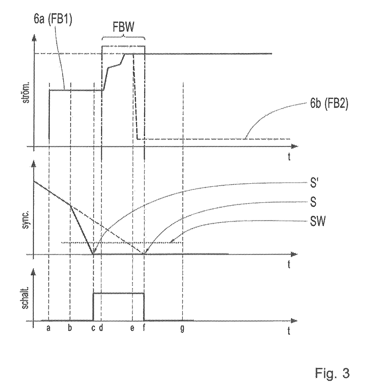
[0012]The object of the present invention is to provide a power-split transmission device and a method for operating it, which take into account an unexpected increase of the deceleration dynamic during a driving range change FBW in such manner that the vehicle drive-train is protected against unfavorable operating conditions.
[0015]The result of this is that when the preparation of the new range clutch is too late because of an increased deceleration dynamic, as occurs for example when driving up a mound, a driving range change FBW is accelerated so that the time during which the transmission ratio remains at the synchronous point, and the drive engine is therefore slowed, are minimized, without interruption of the force locking. This leads to improved driving comfort and better control of the vehicle by the driver, without damaging the transmission device. Since therefore, compared with the normal case, the driving range change in this special situation is completed earlier, the transmission device can correspondingly change the transmission ratio earlier again to smaller reciprocal transmission ratios. This reduces the slowing of the engine accordingly.
[0016]Preferably, the range clutches involved in the driving range change FBW are in the form of hydraulically actuated disk clutches, whereas an electronic control unit controls the filling of the range clutches with hydraulic oil. In this context it is preferably provided that to initiate a driving range change FBW the control unit pre-fills the first range clutch FB2 with hydraulic oil in order to bring the clutch disks already into mutual contact without completing the friction locking of the clutch. By virtue of this clutch pre-filling the range clutch for the first driving range FB2 can be prepared in good time for the driving range change FBW, so that the change can be carried out accurately and with minimum delay.
[0031]Moreover, a detection of the position of the accelerator pedal and / or the brake pedal of the vehicle can also be taken into account, from which the information can be deduced that the driver of the vehicle wants to slow down. This indicates an increased probability that the special situation may arise.

Problems solved by technology

The control rate or speed of change of the transmission ratio in the area of the transmission device is therefore disadvantageously too low to avoid unacceptably large falls of the rotational speed of the drive engine when driving onto a mound or suchlike.
This may for example cause a Diesel engine to slow down to a sometimes unacceptable extent and, in the extreme case, to stall.
A further problem arises in that the time interval before the synchronous point is reached during the driving range change is calculated from the current actual or nominal dynamics.
In such a case the new range clutch would not yet be prepared in time by pre-filling and the driving range change FBW could only take place with some delay.

Method used


Image

  • Transmission device and method for operating the same
  • Transmission device and method for operating the same
  • Transmission device and method for operating the same

Examples


Embodiment Construction

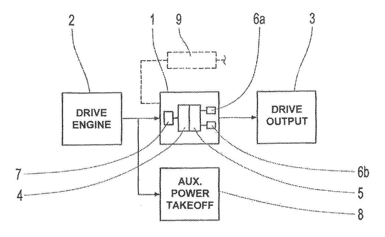
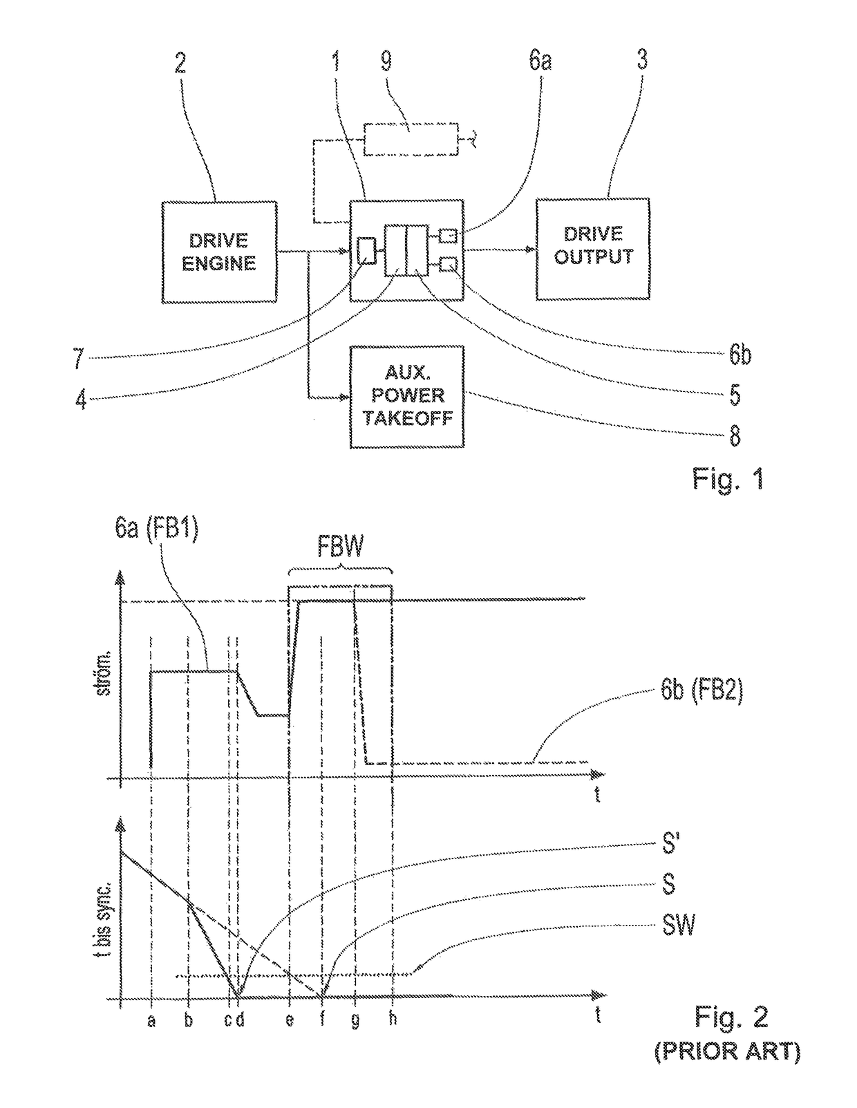
[0040]As shown in FIG. 1 a vehicle drive-train with a continuously variable power-split transmission arrangement 1 comprises a drive engine 2 connected thereto on the input side, which in this example embodiment is in the form of an internal combustion engine. On its output side the transmission device 1 is functionally connected to a drive output 3, whereby a drive torque produced by the drive engine 2 is transmitted in the area of the drive output 3, correspondingly converted as a function of the transmission ratio set in the transmission device 1, to produced a corresponding traction force.

[0041]The transmission device 1 comprises a hydrostatic unit 4 for the continuous adjustment of the transmission ratio, which cooperates with a transmission unit 5. The transmission unit 5 contains shiftable gearsets for various driving ranges, which can be in the form of planetary or spur gear stages. Two example range clutches 6a and 6b cooperate with the transmission unit 5, to couple the tr...


PUM


Abstract

A power-split transmission device for a vehicle, which connects a drive engine to a drive output, having a hydrostatic unit for continuous adjustment of the transmission ratio at a transmission unit, and two range clutches that alternately operate for respectively associated driving ranges with different transmission ratios. A control unit, during regular vehicle deceleration, implements the driving range change from a first range, with higher transmission ratios, to a second range, with lower transmission ratios, by switching from the first to the second range clutch in accordance with a synchronous point dependent deceleration control logic. In the special case of an unexpected increase of the deceleration dynamic at the beginning of an already initiated driving range change from the first to the second driving range, the control unit immediately forces the change by bypassing the synchronous point dependent deceleration control logic when other boundary conditions are fulfilled.

Description

[0001]This application claims priority from German patent application serial no. 10 2016 200 989.3 filed Jan. 25, 2016.FIELD OF THE INVENTION[0002]The invention concerns a power-split transmission device for a vehicle and a method for operating such a transmission device, which can in particular be used in a mobile working machine.BACKGROUND OF THE INVENTION[0003]Vehicle drive-trains of mobile working machines, in particular wheel loaders, are more and more often made with continuously power-split transmission devices, usually equipped with a variator, a reversing transmission and range clutches. In the area of the transmission unit associated with the variator, spur gear stages or planetary stages are usually provided. Driving ranges within which a transmission ratio can be varied continuously by the variator are provided by the transmission unit. To carry out driving range changes, as a rule disk clutches are used as shifting elements. Moreover, the variator is often designed as a...

Claims


Application Information

Patent Timeline
Patent Type & Authority Patents(United States)
IPC IPC(8): F16H61/40F16H47/02
CPCF16H47/02F16H61/40F16H61/702B60K2025/026B60Y2200/415B60Y2400/72F16H2306/20
Inventor GEIGER, SIMONMADLENER, MATTHIASBIEBER, SVEN
Owner ZF FRIEDRICHSHAFEN AG
Learn More