
Method for operating a motor vehicle comprising a power take-off unit

a technology for motor vehicles and power take-offs, which is applied in the direction of clutches, mechanical equipment, transportation and packaging, etc., can solve the problems of reducing vehicle efficiency, and achieve the effect of reducing system pressure and reducing system pressure for actuating the power take-off clutch

Active Publication Date: 2022-06-16
ZF FRIEDRICHSHAFEN AG
View PDF4 Cites 0 Cited by
  • Summary
  • Abstract
  • Description
  • Claims
  • Application Information

AI Technical Summary

Benefits of technology

The patent describes a method for operating a motor vehicle with a power take-off and a driving transmission. The power take-off can be connected to the driving transmission through a frictional clutch, which can be engaged or disengaged by a hydraulic or electro-mechanical means. The method includes detecting a request to connect the power take-off, checking whether relevant boundary conditions are fulfilled, and actuating the clutch to connect the power take-off. The method also includes detecting the pressure required to engage the clutch, and confirming the engagement of the clutch through a confirmation signal. The method can also involve modifying the driving transmission control unit to actuate the shifting elements with higher pressure than usual. The technical effect of the patent is to provide a more efficient and effective method for operating a motor vehicle with a power take-off and a driving transmission.

Problems solved by technology

The system pressure is only built up when necessary, since energy is required for its building up and maintenance, and otherwise the efficiency of the vehicle would decrease.

Method used


Image

  • Method for operating a motor vehicle comprising a power take-off unit

Examples


Embodiment Construction

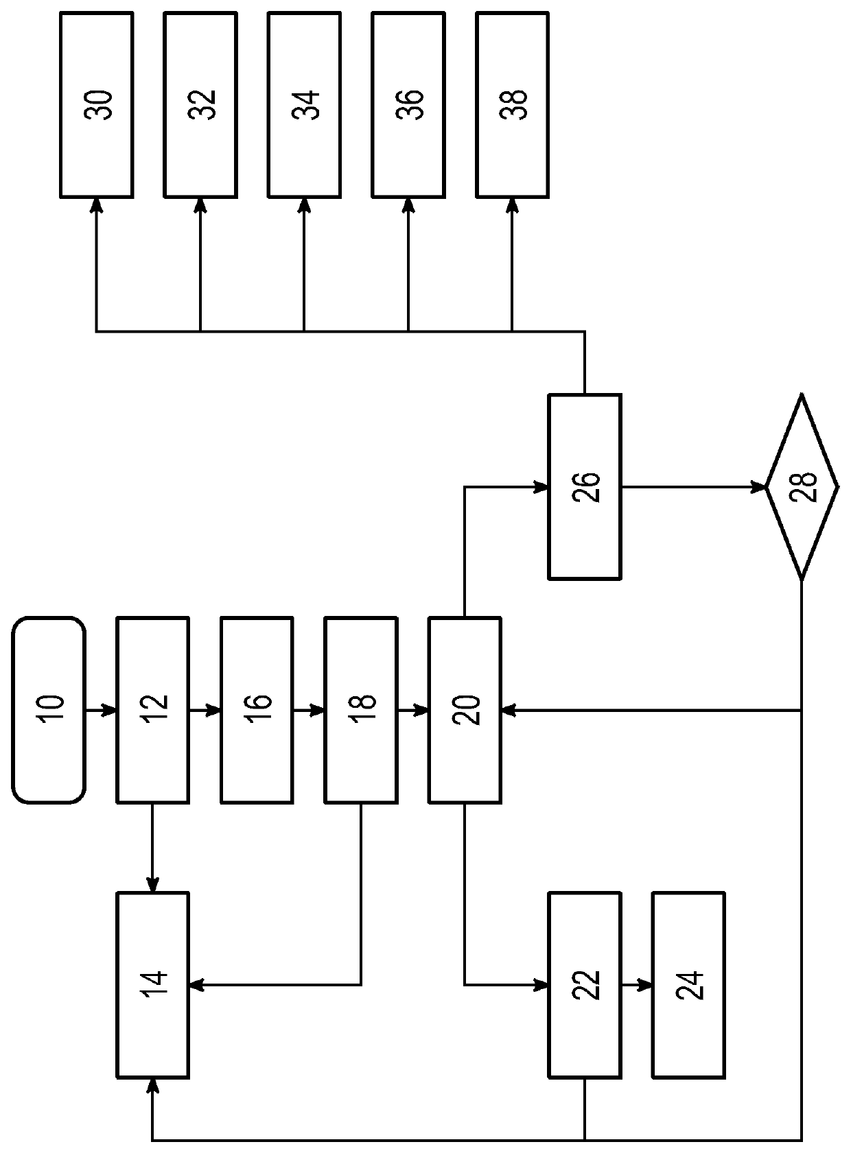
[0032]The sole FIG. clearly but schematically illustrates, in the form of a flow chart, a method for operating a motor vehicle. The motor vehicle has a motor, a driving transmission with at least one shifting element, a power take-off and a power take-off clutch by means of which the power take-off can be connected to the driving transmission. The method can be, for example, provided in the form of a computer-implemented program product. For this, a corresponding software code and a non-volatile data carrier can be provided. The method can be, for example, implemented on a transmission control unit of the motor vehicle, which is connected to the CAN bus of the motor vehicle.

[0033]Step 10 is the start of the method. In step 10 a request to couple the power take-off is detected. For example, the driver of the motor vehicle can actuate a corresponding operating element whereby the transmission control unit receives an actuation signal.

[0034]In step 12, it is checked whether respective ...


PUM


Abstract

The present invention relates to a method for operating a motor vehicle. A request for coupling a power take-off is detected. It is checked (12) whether relevant boundary conditions for coupling the power take-off are fulfilled. If the boundary conditions are fulfilled, a system pressure for actuating the power take-off clutch is built up (16). It is checked (18) whether sufficient system pressure to actuate the power take-off clutch has been built up. When sufficient system pressure has been built up, a confirmation signal is produced (20). In reaction to the confirmation signal, a driving transmission control unit is modified (34) in order to actuate the at least one shifting element of the driving transmission with a higher actuation pressure than with an unmodified driving transmission control unit.

Description

[0001]This application claims priority from German Patent Application No. 10 2020 215 661.1 filed Dec. 10, 2020.FIELD OF THE INVENTION[0002]The present invention relates to a method for operating a motor vehicle with a power take-off. In addition, the invention relates to a control unit designed to carry out the method, and to a corresponding computer program for carrying out the method by means of the said control unit.BACKGROUND OF THE INVENTION[0003]Motor vehicles can not only power a drive input, with their motor, but also provide power for an auxiliary aggregate by way of a power take-off. For example, in the case of agricultural machines, such as tractors or combine harvesters, the motor also supplies power to respective working attachments as auxiliary aggregates. For example, a hydraulic pump can form the power take-off, which is driven in order to be able to use the working attachment such as a grinder or a scoop. The power take-off can be, for example, driven by a motor-si...

Claims


Application Information

Patent Timeline
Patent Type & Authority Applications(United States)
IPC IPC(8): B60W30/188B60K25/06B60K23/00B60K17/28F16D48/02B60W10/02B60W10/11B60W10/04
CPCB60W30/1888B60W2710/1022B60K23/00B60K17/28F16D48/02B60W10/02B60W10/11B60W10/04F16D2500/10437F16D2500/1064F16D2500/108F16D2500/3024F16D2500/3067F16D2500/30806F16D2500/3065B60W2300/15B60W2710/081B60W2710/0644B60W2710/086B60W2710/0677B60W2400/00B60W2710/021B60W2710/1005B60W2710/1083B60W2710/1011B60K25/06B60K17/02B60K17/00B60K2025/065F16D48/06F16D2500/3027F16D2500/3166F16D2500/50825F16D2500/50841B60Y2200/221B60Y2200/222
Inventor LANG, ULF
Owner ZF FRIEDRICHSHAFEN AG
Learn More