Constant pressure hydraulic circuit with relief protection independent of pressure circuit

a hydraulic circuit and constant pressure technology, applied in the field of constant pressure hydraulic circuits with relief protection independent of pressure circuits, can solve the problems of rapid increase in hydraulic fluid pressure, no means to quickly evacuate hydraulic fluid inside the system, and buildup of additional pressure, so as to reduce system pressure, prevent damage, and accelerate the effect of ra

Active Publication Date: 2016-11-03
KUHN KRAUSE
View PDF10 Cites 8 Cited by
  • Summary
  • Abstract
  • Description
  • Claims
  • Application Information

AI Technical Summary

Benefits of technology

[0010]Because the flow capacity of the power beyond return port is higher than that of the SCV, excess hydraulic fluid returns to the reservoir and relieves system pressure at a faster rate when equipped with the pressure relief valve. Furthermore, t

Problems solved by technology

Under certain conditions the hydraulic fluid pressure can rapidly increase due to operator error, an abrupt change in terrain or impact with an obstacle, such as a rock or tree stump.
If hydraulic fluid stops flowing within the circuit for any reason, the hydraulic circuit is then effectively locked and, if hydraulic pressure increases rapidly, there is no means to quickly evacuate the hydraulic fluid inside the system to prevent buildup of a

Method used


Image

  • Constant pressure hydraulic circuit with relief protection independent of pressure circuit
  • Constant pressure hydraulic circuit with relief protection independent of pressure circuit
  • Constant pressure hydraulic circuit with relief protection independent of pressure circuit

Examples


Embodiment Construction

[0023]In the drawings, like reference numerals designate identical or corresponding parts throughout the several views. Further, as used herein, the words “a”, “an” and the like generally carry a meaning of “one or more”, unless stated otherwise. The drawings are generally drawn to scale unless specified otherwise or illustrating schematic structures.

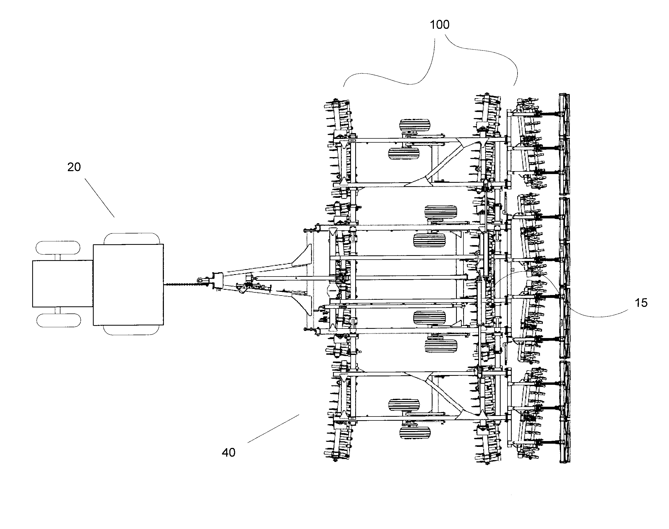
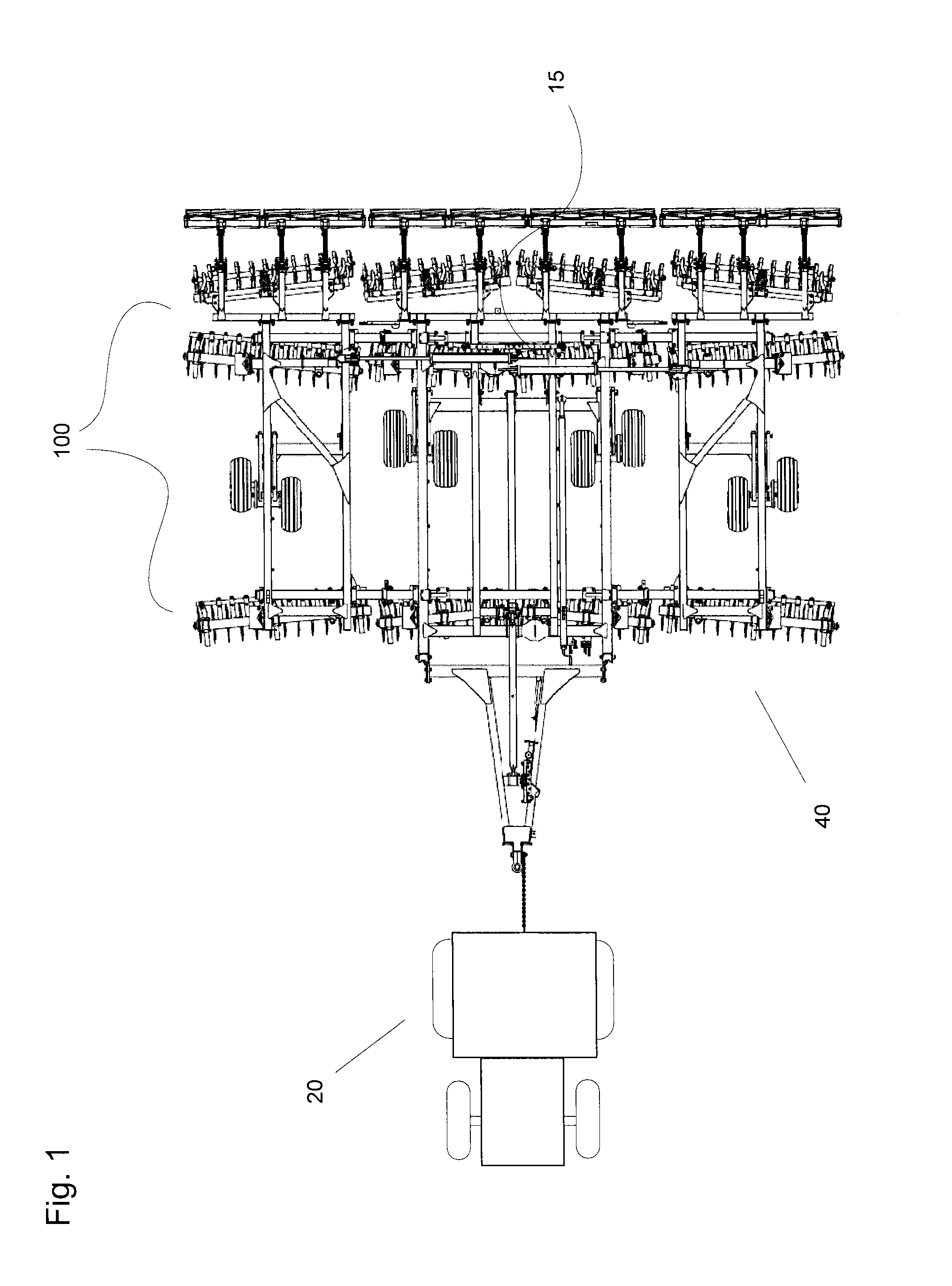
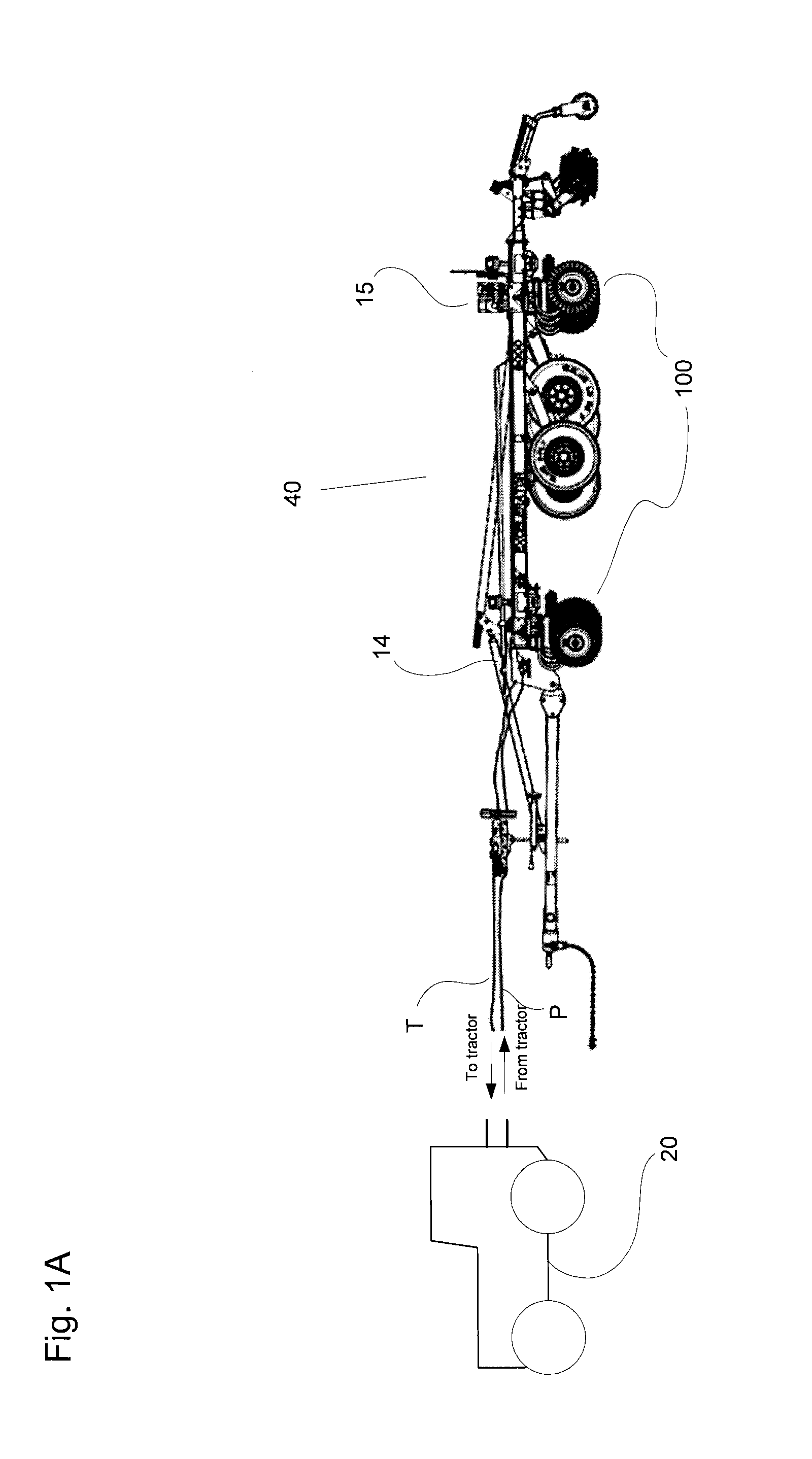
[0024]The term “pressure reduction valve” refers to an apparatus that limits exit pressure to a predetermined maximum value while the term “pressure relief valve” refers to an apparatus that limits incoming pressure to a predetermined maximum value. The term “tractor” refers to a towing vehicle which contains a hydraulic pressure circuit that supplies pressurized hydraulic fluid to a towed vehicle, in this embodiment an agricultural implement.

[0025]The term “hydraulic cylinder”, except where specified, refers to a hydraulic cylinder containing a double-acting piston, which can be actuated by hydraulic fluid on both sides of the piston, ...


PUM


Abstract

A hydraulic circuit for an agricultural implement consisting of a hydraulic cylinder that exerts a force on a component of the implement. A pressure reduction valve located between a hydraulic power source and the hydraulic cylinder maintains pressure to no more than a preset maximum to protect the hydraulic cylinder by routing excess hydraulic fluid back through a hydraulic line into a reservoir. A pressure relief valve with a preset maximum pressure greater than that of the pressure reduction valve is located between the pressure reduction valve and the hydraulic cylinder, and is connected to the reservoir through a dedicated return line. If hydraulic fluid pressure in the circuit increases to greater than the maximum of the pressure reduction valve, hydraulic fluid is diverted back to the reservoir through the pressure relief valve and a dedicated return line.

Description

BACKGROUND[0001]1. Field of the Disclosure[0002]The present disclosure relates to agricultural and earthmoving implements, generally relating to implements for tilling, plowing and seeding, equipped with hydraulic control systems, and more specifically, to structure for providing constant pressure relief protection from excessive or sudden hydraulic pressure increases within a system designed to exert a constant downward force on the ground.[0003]2. Description of the Related Art[0004]This disclosure pertains to agricultural and earth moving implements operated hydraulically. A hydraulic system enables an implement to be raised and lowered. While in a lowered position, the hydraulic system maintains a constant downward pressure between an implement, such as agricultural components, and the ground surface, as described, for example, in U.S. Pat. No. 5,065,681.[0005]However, due to many possible factors including, for example, slopes and topographical variations of the ground surface,...

Claims


Application Information

Patent Timeline
IPC IPC(8): A01B63/32F15B11/10A01B61/00
CPCA01B63/32A01B61/00F15B2211/6336F15B2211/50554F15B11/10F15B11/028F15B13/024F15B13/025F15B2211/3054F15B2211/50518F15B2211/5153F15B2211/5159F15B2211/55F15B2211/6313F15B2211/7053
Inventor FINK, JEROME THOMASHAGMAN, RODNEY LEE
Owner KUHN KRAUSE
Why Eureka
Try Eureka