
Polishing pad and method for producing polishing pad

a technology of polishing pads and polishing pads, which is applied in the field of polishing pads, can solve the problems of polishing scratches and the tendency of conventional wet polishing pads to have a problem, and achieve the effects of reducing the formation of defects, and stable film formability

Active Publication Date: 2018-09-11
FUJIBO HLDG
View PDF29 Cites 5 Cited by
  • Summary
  • Abstract
  • Description
  • Claims
  • Application Information

AI Technical Summary

Benefits of technology

[0023]The polishing pad and the method for producing the same of the present invention makes it possible to provide a polishing pad which achieves reduced formation of defects and which has stable film formability.
[0024]The method for producing a polishing pad of the present invention reduces the localization, aggregation, and the like of the insoluble content (insoluble component), so that the obtained polishing pad achieves reduced formation of defects during polishing. In addition, since the poor solvent is added in an amount satisfying Formula 1, a polishing layer comprising a polyurethane resin film can be obtained with stable film formability, even with a formulation not containing an additive such as carbon black. Moreover, owing to the appropriate coagulation value of the polishing layer of the polishing pad of the present invention, partial wear due to uneven slurry circulation is less likely to occur during polishing. Hence, formation of defects due to sludge accumulation can be suppressed. When the hardness, the number of foamed cells, the current value (=friction resistance), or the like is within the preferred range, the polishing efficiencies (the rate and the uniformity) are excellent.

Problems solved by technology

However, conventional wet polishing pads still have a problem of a high tendency to cause polishing scratches.

Method used


Image

  • Polishing pad and method for producing polishing pad
  • Polishing pad and method for producing polishing pad

Examples


example 1

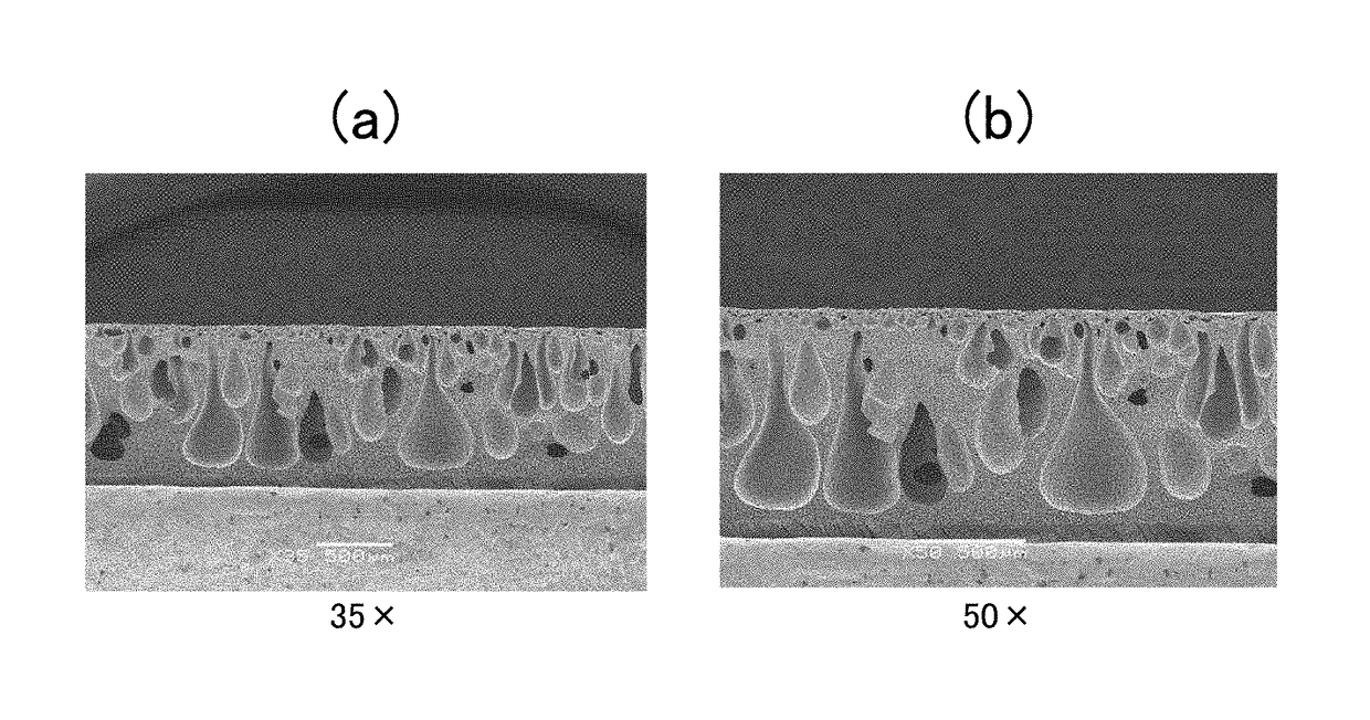
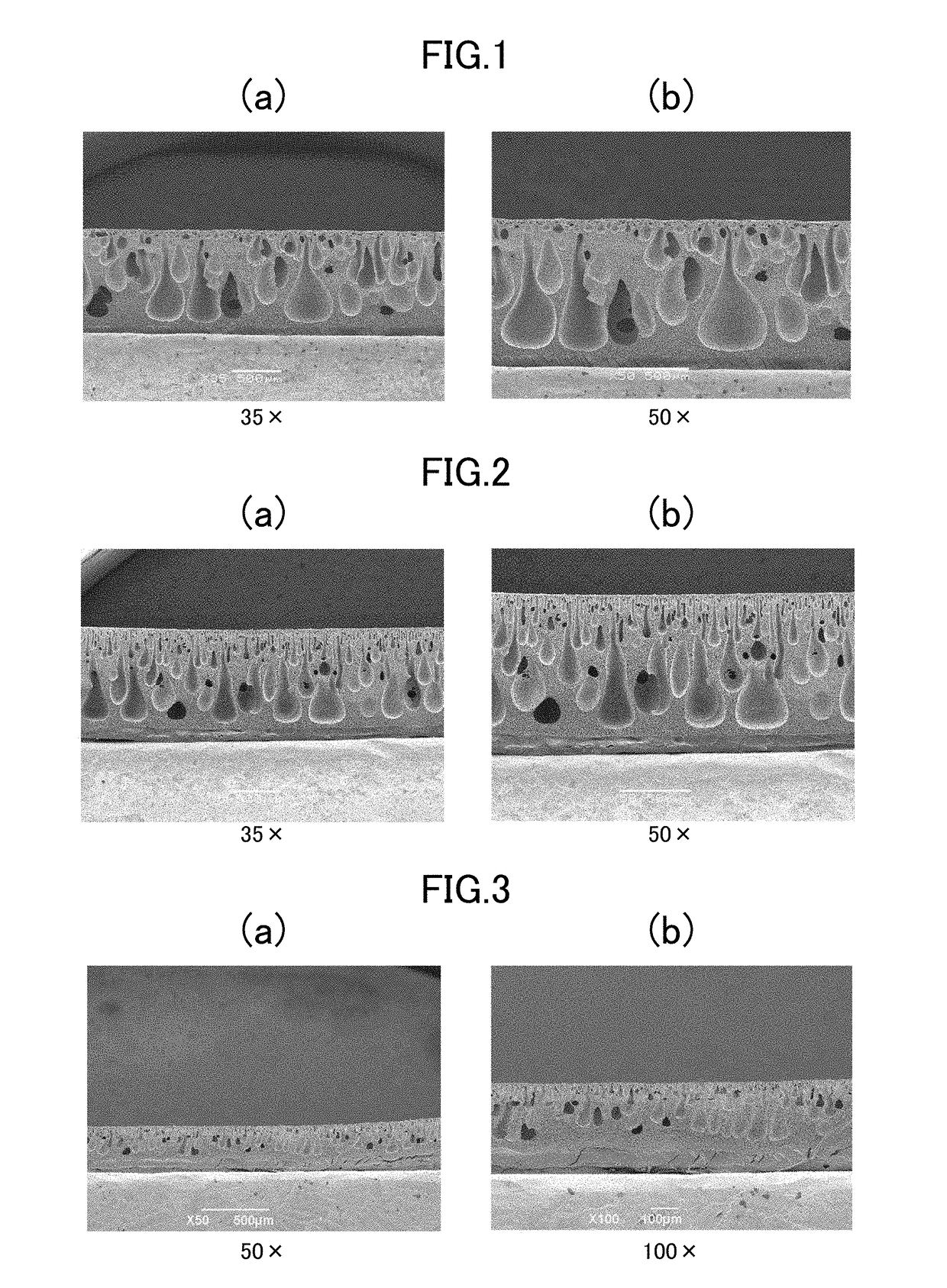
[0096]A resin-containing solution was obtained by adding 60 parts by mass of DMF and 5 parts by mass water to 100 parts by mass of a solution containing a polyester-based polyurethane resin (30 parts by mass) having a coagulation value (determined by using water as a poor solvent) of 10.8 as shown in Table 1 below and DMF (70 parts by mass), followed by mixing.

[0097]The obtained resin-containing solution was filtered to remove insoluble components. The solution was cast onto a polyester film. After that, the polyester film on which the resin-containing solution was cast was immersed in a coagulation bath (the coagulation liquid was water), and coagulation from the resin-containing solution was conducted, followed by washing and drying. Thus, a resin film was obtained. A top surface of the obtained resin film was subjected to a grinding treatment, and then the resin film and a double-sided tape was laminated on each other. Thus, a polishing pad was obtained. Note that “parts” in Tabl...


PUM

PropertyMeasurementUnit
pore diameteraaaaaaaaaa
temperatureaaaaaaaaaa

Abstract

Provided are a method for producing a finish polishing pad and the polishing pad which allow formation of a stable film and enables polishing with fewer polishing scratches. The method includes the steps of: dissolving a composition for forming polyurethane resin film containing a polyurethane resin and an additive(s) in a solvent capable of dissolving the resin; removing an insoluble component(s) to make the content of the insoluble component(s) in the solution less than 1% by mass relative to the total mass of the composition; adding a poor solvent to the solution from which the insoluble component(s) has(have) been removed, followed by mixing, the amount of the poor solvent added being calculated according to a defined Formula 1; and forming a film from the mixture solution on the film formation substrate by a wet coagulation method, to thereby form the polyurethane resin film.

Description

TECHNICAL FIELD[0001]The present invention relates to a polishing pad and a method for producing the same. More particularly, the present invention relates to a finish polishing pad capable of achieving reduced formation of defects in bare silicon, semiconductor devices, and magnetic disk, and a method for producing the same.BACKGROUND ART[0002]Polishing pads used for polishing semiconductor devices and the like are generally classified into hard ones and soft ones. Hard polishing pads are prepared mainly based on the dry method in which a urethane prepolymer is formed by chain-extension. Soft polishing pads are prepared mainly based on the wet method in which a urethane resin solution is coagulated in a coagulation bath and dried. Recently, polished workpieces have been required to have high flatness and uniformity, and soft polishing pads have increasingly been used in a finish polishing step and the like.[0003]Especially, it is particularly desirable that a finish polishing step ...

Claims


Application Information

Patent Timeline
Patent Type & Authority Patents(United States)
IPC IPC(8): B24B1/00C08G18/44C08G18/42C08G18/76C08L75/06B24B37/24B24D3/00C08L75/04C08G18/48
CPCB24B37/24C08G18/4238C08G18/44C08L75/06C08G18/4854C08G18/7671C08L75/04C08G18/4825
Inventor TATENO, TEPPEIMIYASAKA, HIROHITOMATSUOKA, RYUMAKANAZAWA, YOSHIEMIYAZAWA, FUMIO
Owner FUJIBO HLDG
Learn More