Specific multi-band antenna impedance matching circuit and tire-pressure monitoring device using same

a multi-band antenna and impedance matching technology, applied in the field of impedance matching circuits, can solve the problems of largely increasing manufacturing costs and difficulties in developing multi-band antennas, and achieve the effect of saving users a lot of costs

Active Publication Date: 2018-09-11
KEYCORE TECH CORP
View PDF13 Cites 13 Cited by
  • Summary
  • Abstract
  • Description
  • Claims
  • Application Information

AI Technical Summary

Benefits of technology

[0006]To effectively solve the problem in the prior art multi-band antennas, it is a primary object of the present invention to provide a specific multi-band antenna impedance matching circuit that can save users a lot of cost.

Problems solved by technology

However, there are difficulties in developing the multi-band antennas.
However, the multiple antenna elements 13, the multiple tunable matching circuits, i.e. the first and the second tunable matching circuit 11, 12, and the switching circuit 15 inevitably cause the problem of largely increased manufacturing cost.

Method used


Image

  • Specific multi-band antenna impedance matching circuit and tire-pressure monitoring device using same
  • Specific multi-band antenna impedance matching circuit and tire-pressure monitoring device using same
  • Specific multi-band antenna impedance matching circuit and tire-pressure monitoring device using same

Examples


first embodiment

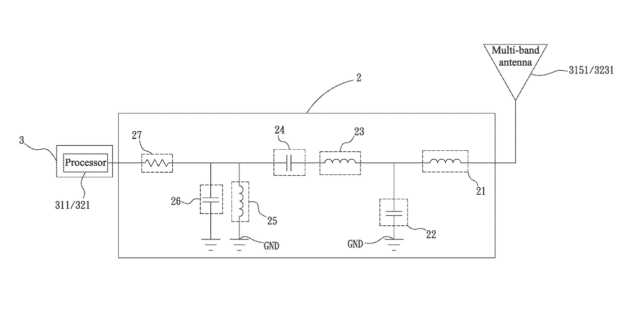
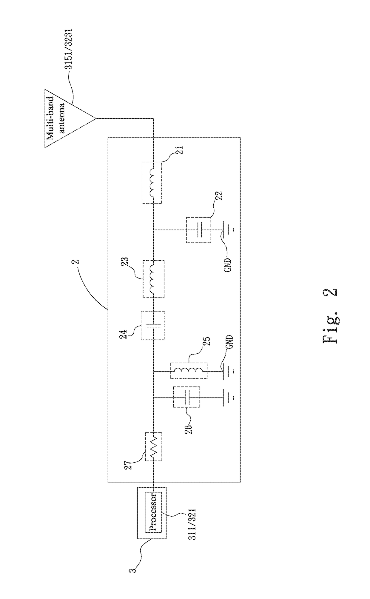
[0034]In the illustrated first embodiment, the first inductance unit 21 has an inductance value between 0.5 nanohenrys (nH) and 10 nH; the second inductance unit 23 has an inductance value between 10 nH and 60 nH; the third inductance unit 25 has an inductance value between 1 nH and 20 nH; the first capacitance unit 22 has a capacitance value between 5 picofarads (pF) and 40 pF; the second capacitance unit 24 has a capacitance value between 5 pF and 40 pF; and the third capacitance unit 26 has a capacitance value between 1 pF and 40 pF. With the above available inductance values of the first, second and third inductance units 21, 23, 25 and the above available capacitance values of the first, second and third capacitance units 22, 24, 26, the antenna impedance matching circuit 2 of the present invention can have stable specific dual-frequency of 315 MHz and 433 MHz and can reject and filter other noises. FIG. 4 is a return loss vs. frequency graph of the wireless transmitter 315 or ...

second embodiment

[0041]It is noted there is not any switching circuit provided between the processor 311 and the antenna impedance matching circuit 2 for switching between different frequencies. That is, the tire-pressure monitoring device 31 is not internally provided with any of the aforesaid switching circuit and accordingly, no switching circuit is connected to between the processor 311 and the antenna impedance matching circuit 2. According to the present invention, when the processor 311 sends the tire-pressure signal and the tire-temperature signal via the wireless transmitter 315, since the specific frequencies of the antenna impedance matching circuit 2 are, for example, 315 MHz and 433 MHz, only one single multi-band antenna 3151 is sufficient for transmitting tire-pressure signal and tire-temperature signal (i.e. wireless signals) having specific frequencies of, for example, 315 MHz and 433 MHz. That is, the effect of transmitting specific multi-band wireless signals, such as RF wireless ...


PUM


Abstract

A specific multi-band antenna impedance matching circuit and a tire-pressure monitoring device using same are disclosed. The antenna impedance matching circuit includes at least one first, one second and one third inductance unit and at least one first, one second and one third capacitance unit. The first capacitance unit is connected at a first end to first ends of the first and the second inductance unit and at a second end to a ground; the second inductance unit and the second capacitance unit are connected in series; the third inductance unit and the third capacitance unit are connected in parallel; and the third inductance unit is connected at a first end to a first end of the second capacitance unit and at a second end to the ground.

Description

FIELD OF THE INVENTION[0001]The present invention relates to an impedance matching circuit and more particularly, to a specific multi-band antenna impedance matching circuit that can save users a lot of cost. The present invention also relates to a tire-pressure monitoring device that uses the specific multi-band antenna impedance matching circuit.BACKGROUND OF THE INVENTION[0002]Due to the constantly improved communication technology, various kinds of wireless communication devices, such as cell phones, have become an indispensable part in people's daily life. Moreover, since people in the modern society often travel for business or fun in different countries, it becomes very important the wireless communication devices is able to receive and transmit multi-band wireless electrical signals.[0003]However, the wireless communication standards vary from area to area in the world. Currently, most of the available wireless communication device designs include a multi-band antenna or inc...

Claims


Application Information

Patent Timeline
Patent Type & Authority Patents(United States)
IPC IPC(8): B60C23/04H01Q21/30H04B1/18H03H7/38
CPCB60C23/0462B60C23/0444H01Q21/30H04B1/18H03H7/38H03H2007/386H01Q1/243H01Q5/50B60C23/0452H04B1/0458
Inventor LIANG, YANG-TECHIU, PO-WEIHSU, SHENG-RUEILIN, WEI-CHENGHSIAO, CHIEN-JENTSENG, SHIH-HSIU
Owner KEYCORE TECH CORP
Why Eureka
Try Eureka