

Pipe connection fitting
a technology for gas pipes and fittings, which is applied in the direction of hose connections, pipe couplings, couplings, etc., can solve the problems of difficult installation of the connection fitting itself, limited space for the connection fitting, and bulky connection fittings, etc., to achieve simple cost effective manufacturing and assembly, reduce material consumption, and facilitate the effect of pipe connection fittings
- Summary
- Abstract
- Description
- Claims
- Application Information
AI Technical Summary
Benefits of technology
Problems solved by technology
Method used
Image

Examples
Embodiment Construction
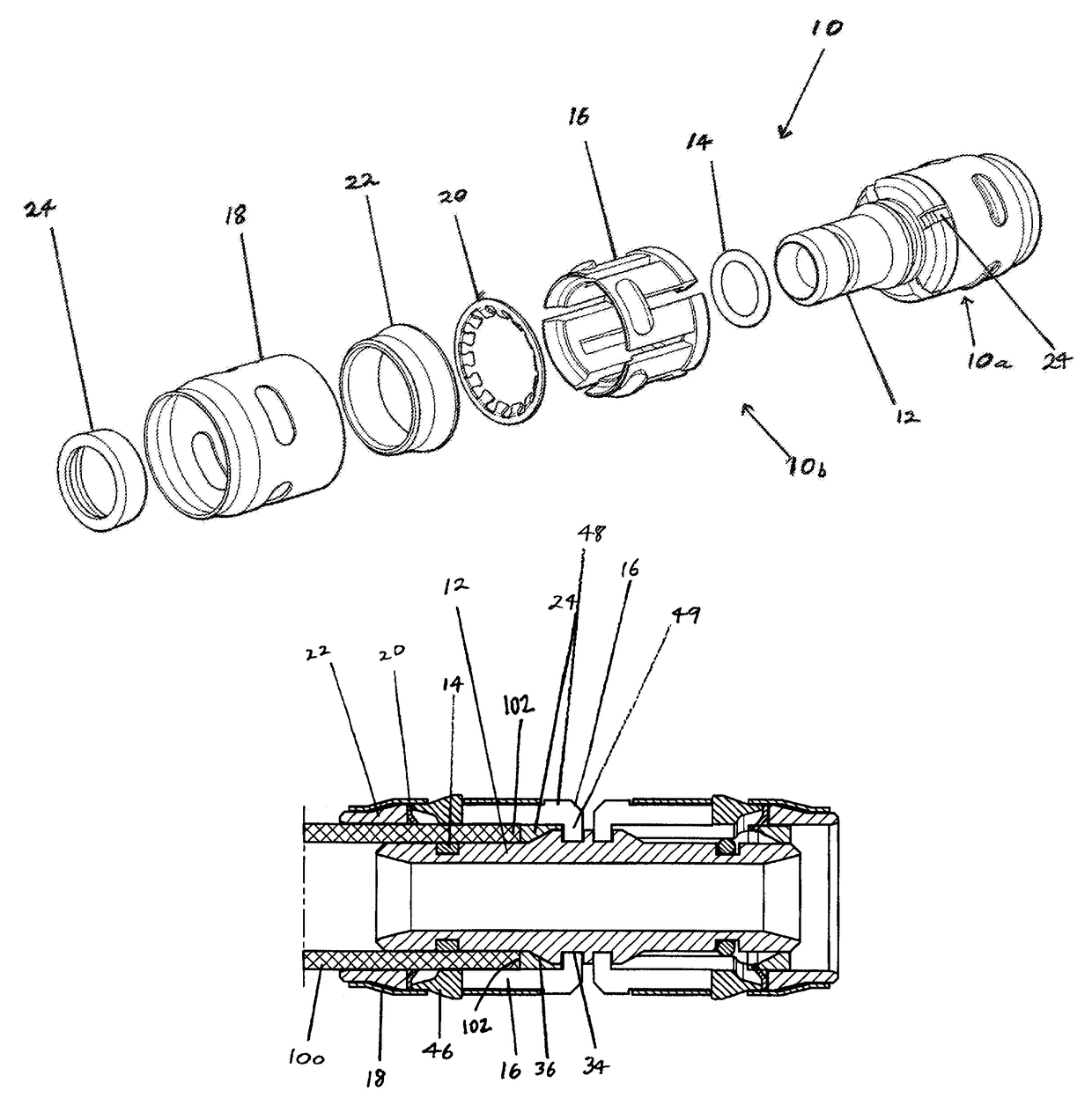
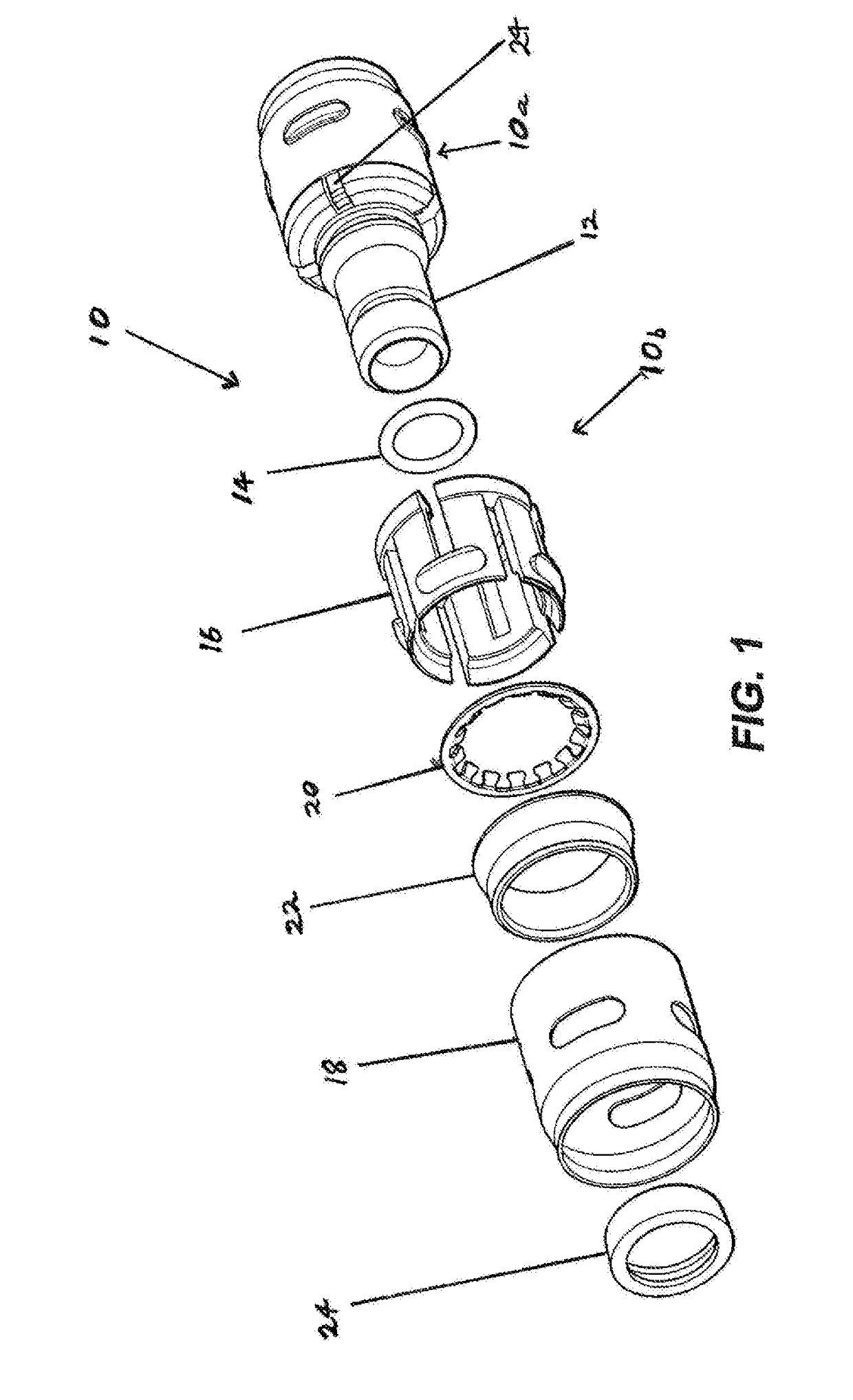
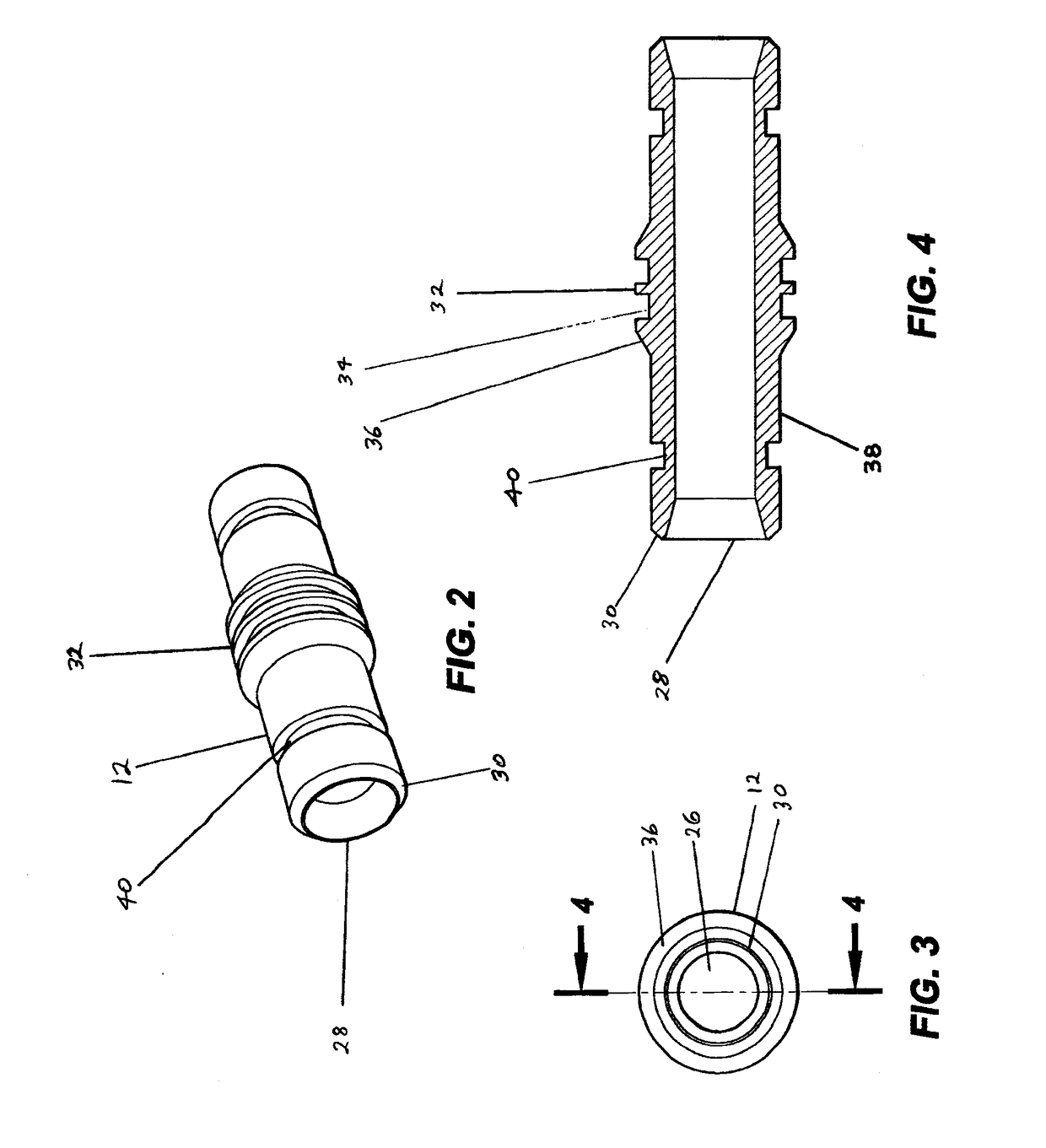
[0009]An advantage of the invention relates to the making of a pipe connection fitting quickly and economically. Preferably, the design of the connection fitting incorporates a plastic collet and stainless steel collet retainer. While other materials may be used, it is important that they be suitable for the uses to which the collet retainer is put. The preferred materials used in these components allow for simple cost effective manufacturing and assembly. The sealing of the pipe is performed by an O-ring on the tubular body which seals on the inside of the pipe. Sealing on the inside of the pipe allows the body and other components of the connection to be smaller in their diameters, which requires less material. This design allows lower cost material and lower manufacturing cost. The invention allows a more cost effective connection fitting to the market.
[0010]The tubular body can be composed of a thermoplastics material or a thermosetting plastics material. Alternatively, it may b...
PUM
 Abstract
Description
Claims
Application Information