Over pressure relief system for fluid ends

a technology of relief valve and fluid end, which is applied in the field of hydraulic fracturing, can solve problems such as extreme pressure buildup

Active Publication Date: 2018-09-25
CATERPILLAR INC
View PDF14 Cites 134 Cited by
  • Summary
  • Abstract
  • Description
  • Claims
  • Application Information

AI Technical Summary

Problems solved by technology

Proppants may get stuck in portions of the fluid end which may cause extreme pressure build up.

Method used


Image

  • Over pressure relief system for fluid ends
  • Over pressure relief system for fluid ends
  • Over pressure relief system for fluid ends

Examples


Embodiment Construction

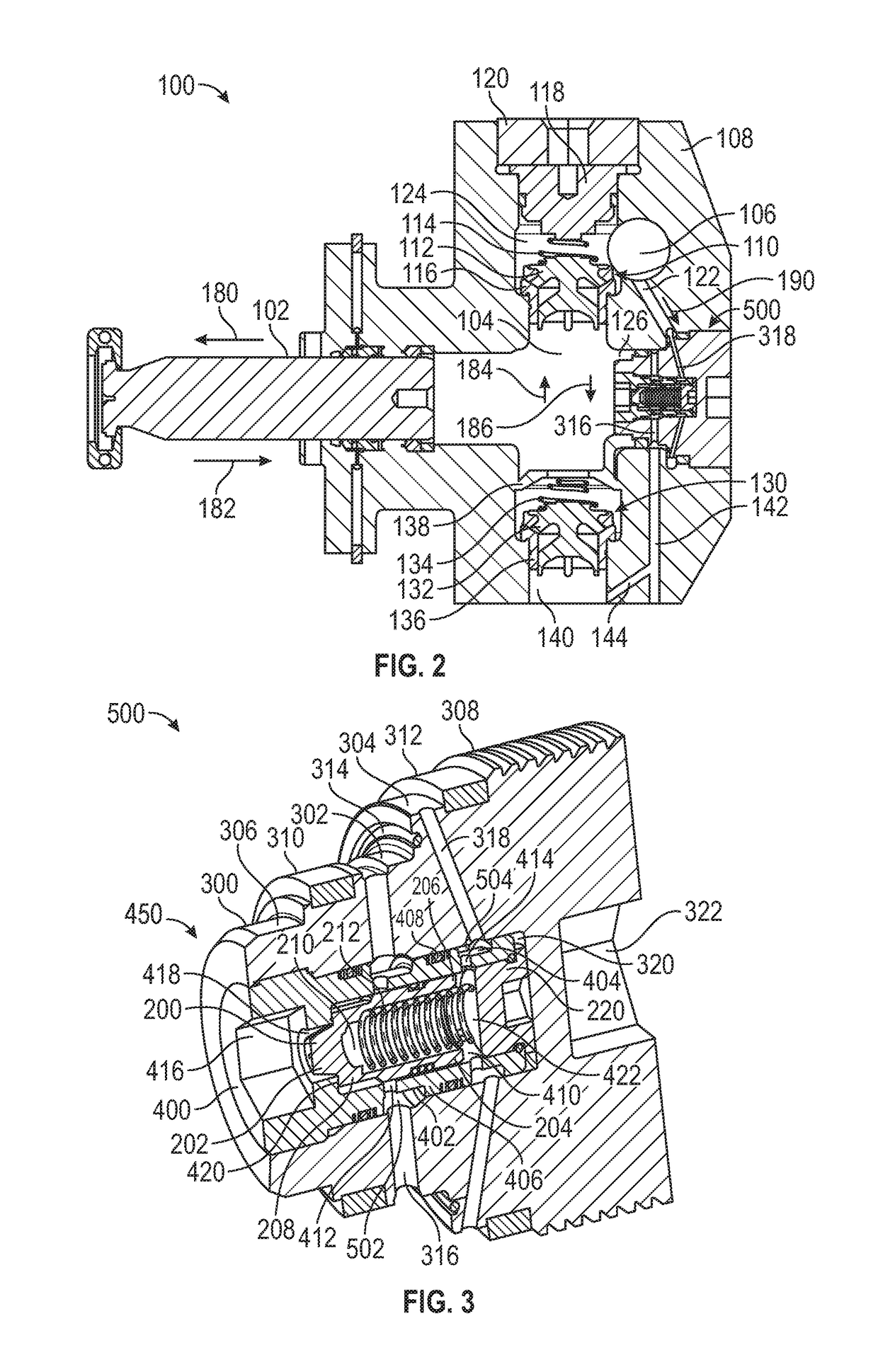
[0012]This disclosure relates to a relief valve assembly for a fluid end. The relief valve assembly provides pressure relief when the fluid end undergoes an overpressure event. The overpressure event can be caused by a valve getting stuck due to various reasons, allowing for the buildup of pressurized fluid mixture in a compression area of the fluid end. The relief valve assembly allows for the pressurized fluid mixture to return to the intake of the fluid mixture, usually a suction cavity. The fluid mixture can then be recycled back into the compression area.

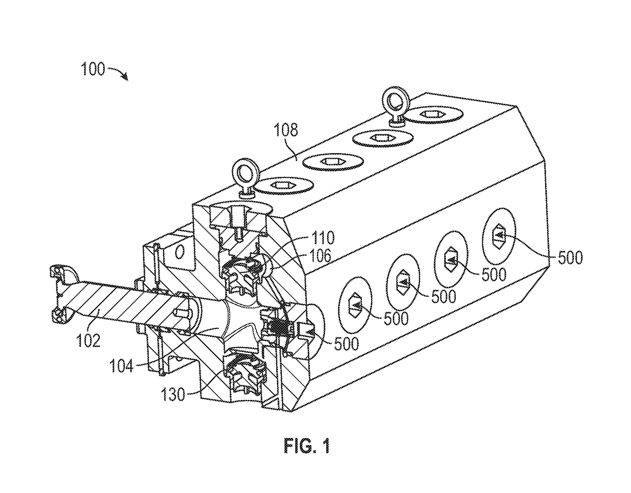
[0013]FIG. 1 is a perspective view illustrating a cross section of a fluid end 100 according to an embodiment of the present disclosure. As shown, fluid end 100 may include a fluid end housing 108, a plunger 102, a compression area 104 (sometimes referred to as a plunger bore), a discharge valve assembly 110, a discharge conduit 106, a suction valve assembly 130, and a relief valve assembly 500. Fluid end housing 108 may enclos...


PUM


Abstract

A relief valve assembly includes a housing assembly defining a chamber therein. The relief valve assembly includes a piston. The piston may be at least partially disposed within the chamber. The relief valve assembly includes a pilot inlet. The pilot inlet may be configured to provide a pilot pressure proximate a second end of the chamber. The relief valve assembly includes an overpressure inlet sealed from a first end of the chamber by the piston. The overpressure inlet may be configured to provide an inlet pressure which may actuate the piston when the inlet pressure exceeds the pilot pressure.

Description

TECHNICAL FIELD[0001]This disclosure relates to hydraulic fracturing in general and, more specifically, to a fluid end having a relief valve assembly.BACKGROUND[0002]Subterranean hydraulic fracturing is conducted to increase or stimulate production from a hydrocarbon well. To conduct a fracturing process, high pressures are used to pump special fracturing fluids, including some that contain “proppants”, down the well-bore and into a hydrocarbon formation to split or “fracture” the rock formation along veins or planes extending from the well-bore. Plunger pumps are commonly used in the oil and gas industry for hydraulic fracturing purposes. Plunger pumps have a fluid end and a power end that drives the fluid end. Proppants may get stuck in portions of the fluid end which may cause extreme pressure build up.[0003]U.S. Pat. No. 7,335,002 to Vicars is directed to a fluid end for a high-pressure pump including a unitary body with a plurality of horizontal passages each for receiving a re...

Claims


Application Information

Patent Timeline
Patent Type & Authority Patents(United States)
IPC IPC(8): F04B49/24F16K17/04F04B53/10F16L17/06F16K27/00F16K17/06F04B53/14F04B19/22E21B43/26
CPCF04B49/24F04B19/22F04B53/10F04B53/143F16K17/065F16K27/003F16K17/04Y10T137/7925E21B43/26Y10T137/7762F04B15/02F04B47/02F04B49/03
Inventor GRAHAM, CURTIS JOHNSTAFL, SAMUEL JAROSLAV
Owner CATERPILLAR INC
Why Eureka
Try Eureka