System and method for modeling of turbo-charged engines and indirect measurement of turbine and waste-gate flow and turbine efficiency

a technology of turbine and wastegate, which is applied in the direction of machines/engines, electric control, instruments, etc., can solve the problems of the inability to know the amount of exhaust gas flowing through the turbine, and the inability to accurately predict the flow of exhaust gas through the turbine, etc., to achieve the effect of convenient implementation

Inactive Publication Date: 2010-07-06
DELPHI TECH INC
View PDF9 Cites 36 Cited by
  • Summary
  • Abstract
  • Description
  • Claims
  • Application Information

AI Technical Summary

Problems solved by technology

Conventional estimation logic for a turbo-charged engine is substantially more complex than the relatively simple models that are known and adequate for a naturally aspirated engine.
Furthermore, it is unknown what amount of the exhaust gas flows through the turbine, on the one hand, versus how much flows through the parallel waste-gate path, on the other hand.
The model in Schopp, however, not only requires a so-called compressor characteristic map, which as known is generally available from the turbo-charger manufacturer, the Schopp model also requires the turbine map, which is more difficult to obtain, and is of questionable validity since it is measured at steady-state conditions, while the conditions on a real-world engine are pulsating.
Moreover, another disadvantage of the Schopp model is that it may become unstable, especially near its limit of operation, and accordingly special care is required in configuring it for use, which makes any actual implementation challenging.

Method used


Image

  • System and method for modeling of turbo-charged engines and indirect measurement of turbine and waste-gate flow and turbine efficiency
  • System and method for modeling of turbo-charged engines and indirect measurement of turbine and waste-gate flow and turbine efficiency
  • System and method for modeling of turbo-charged engines and indirect measurement of turbine and waste-gate flow and turbine efficiency

Examples


Embodiment Construction

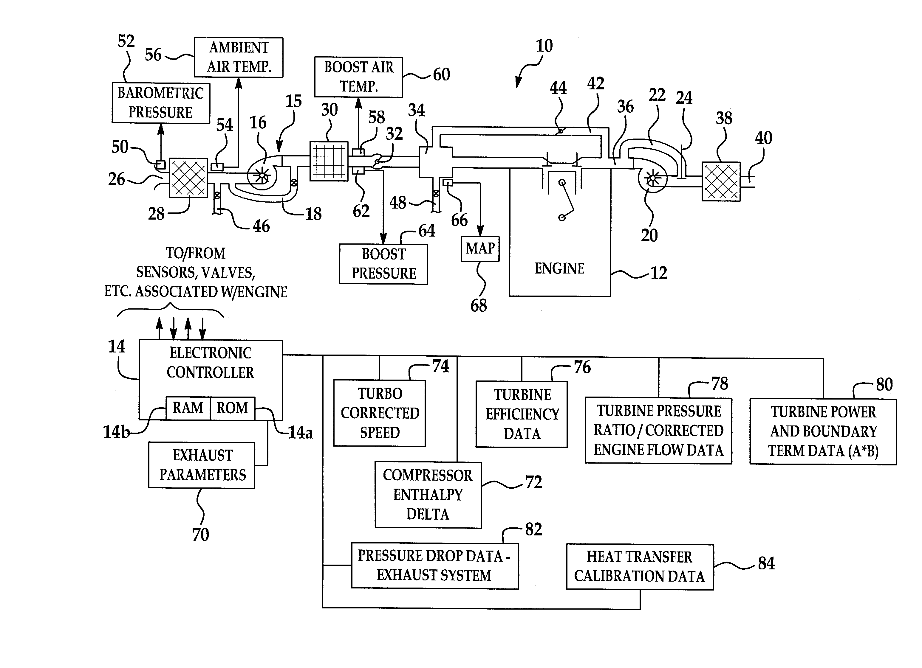
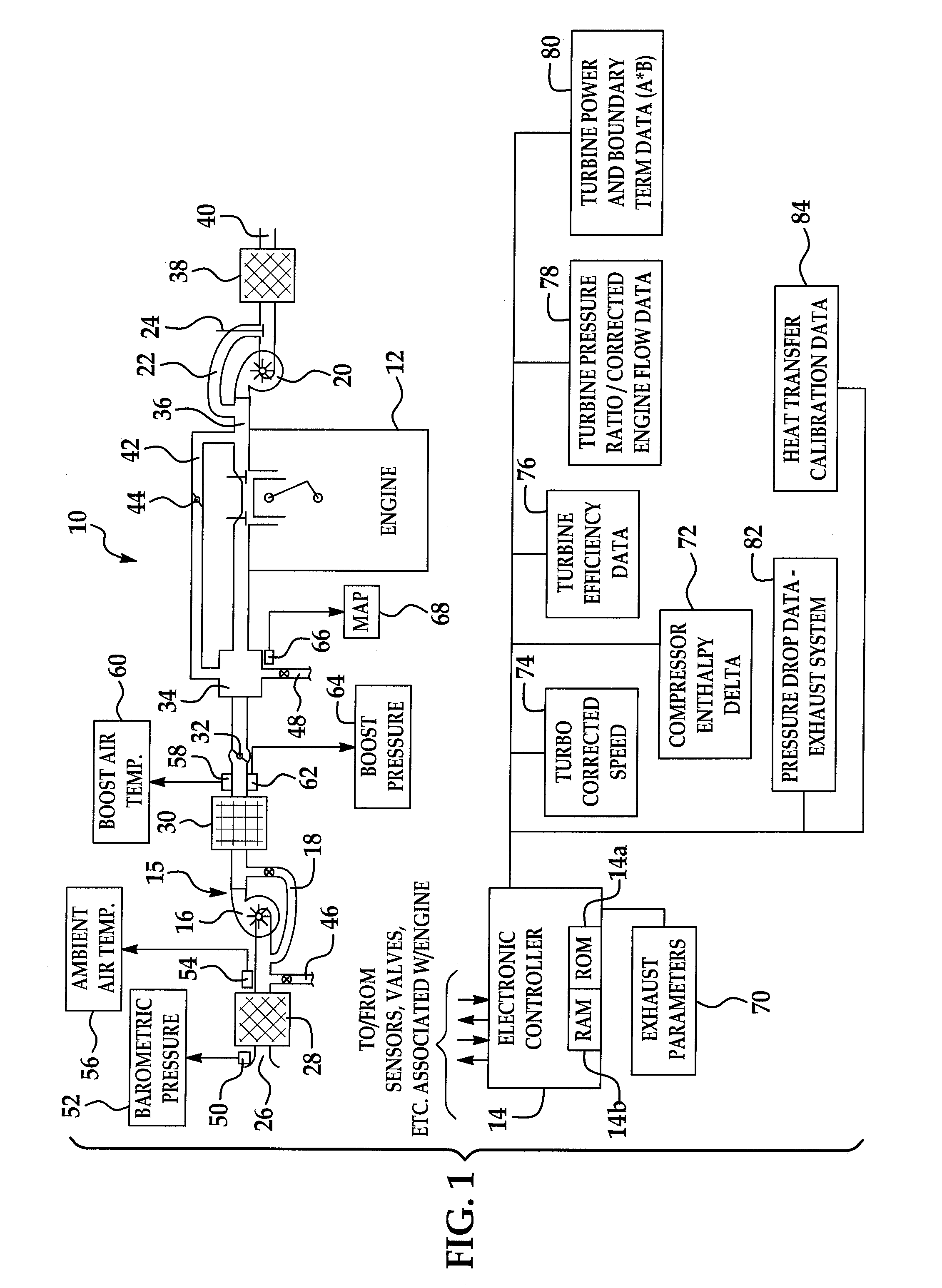
[0017]Referring now to the drawings wherein like reference numerals are used to identify identical components in the various views, FIG. 1 is a diagrammatic view of a turbo-charged internal combustion engine system 10 configured in accordance with the present invention. The system 10 includes an internal combustion engine 12 controlled by an electronic engine controller 14 all in accordance with the present invention.

[0018]Engine 12 may be a spark-ignition engine that includes a number of base engine components, sensing devices, output systems and devices, and a control system. Alternatively, the present invention may be used with compression-ignition engines, such as diesel or the like.

[0019]Generally, electronic controller 14 is configured via suitable programming to contain various software algorithms and calibrations, electrically connected and responsive to a plurality of engine and vehicle sensors, and operably connected to a plurality of output devices. Controller 14 includes...


PUM


Abstract

A real-time system for modeling a turbo-charged engine includes a model configured to estimate various exhaust states such as turbine inlet pressure, turbine outlet pressure, turbine outlet temperature, turbine mass flow rate and waste-gate valve mass flow rate. The model is dependent only on the availability of normal operating values available in a conventionally-configured automotive controller and one or more measured intake side parameters such as ambient pressure, boost pressure, ambient temperature and compressor mass flow rate. The model is constructed to reflect a high-level application of energy conservation between the turbine (generated power) and compressor (absorbed power). A method for the indirect measurement of turbine and waste-gate flow uses turbine inlet and outlet pressure, inlet temperature and engine mass air flow rate measurements. A method for the indirect measurement of turbine efficiency avoids the need for manufacturer's turbine data.

Description

TECHNICAL FIELD[0001]The present invention relates to a system and method for modeling of turbo-charged engines to estimate various exhaust parameters as well as to provide an indirect measurement of waste-gate and turbine flow and turbine efficiency.BACKGROUND OF THE INVENTION[0002]A turbo-charged internal combustion engine includes additional components and physical processes in both the intake and exhaust stream. On the intake side of the engine, a centrifugal compressor and intercooler are provided and are located between the air cleaner and a throttle valve. On the exhaust side, a turbine and a waste-gate—which defines a parallel exhaust stream path with the turbine—are both located between the exhaust manifold and the catalyst / muffler. It is known to provide an engine management system (EMS) configured to control the operation of a turbo-charged engine. However, such an EMS is conventionally configured to perform its functions with only a minimal amount of additional informati...

Claims


Application Information

Patent Timeline
Patent Type & Authority Patents(United States)
IPC IPC(8): F02D23/00
CPCF02D41/0007F02D41/1445F02D41/1447F02D41/145G06F17/5009G06F17/5095F02D2041/1433G06F2217/16G06F2217/80Y02T10/82Y02T10/144G06F2119/08G06F2111/10G06F30/15G06F30/20Y02T10/12
Inventor MULLER, MARTIN
Owner DELPHI TECH INC
Why Eureka
Try Eureka