Pilot operated pressure valve

a technology of pressure valve and pilot, which is applied in the direction of fluid pressure control, process and machine control, instruments, etc., can solve the problems of excessively abrupt energizing of the hydraulic motor, operation detrimental, and equipment being operated will exhibit too sharp start-up

Inactive Publication Date: 2003-11-04
SUN HYDRAULICS
View PDF7 Cites 34 Cited by
  • Summary
  • Abstract
  • Description
  • Claims
  • Application Information

AI Technical Summary

Problems solved by technology

As a result, there is a sharp hydraulic spike in the pressure level of the fluid system which results in excessively abrupt energizing of the hydraulic motor.
Not only is this operational limitation abusive to the system, but it may also be operationally detrimental in that the equipment being operated will exhibit too sharp a start-up.
A general technical problem with the above relief valves concerns the principal embodied in each that depends upon a very high pressure drop across a pilot orifice which varies somewhat proportional to inlet pressure.
However, the flow across such arrangements is viscosity sensitive.
The friction of the moveable piston in each of these devices is a source of yet another problem in l

Method used


Image

  • Pilot operated pressure valve
  • Pilot operated pressure valve
  • Pilot operated pressure valve

Examples


Embodiment Construction

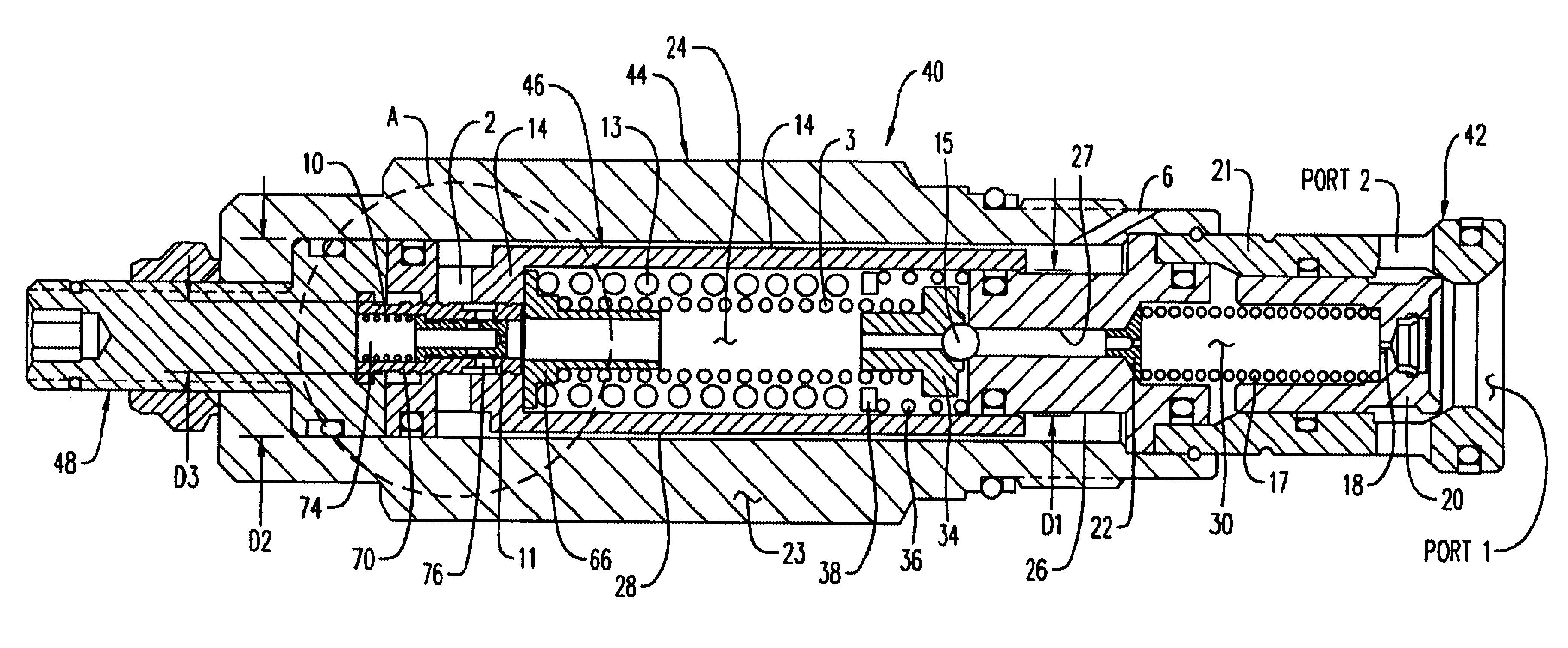
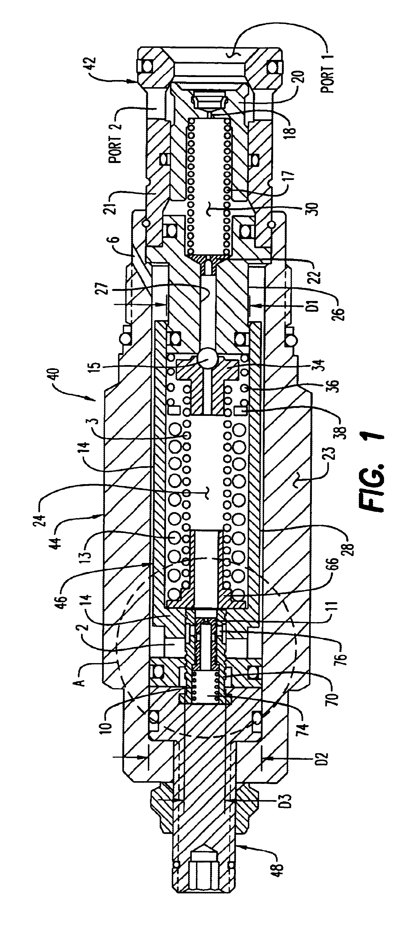
The basic structure of the present invention as above described may be easily modified within the intended scope of this invention. One such alternate embodiment is in the form of a vented relief valve achieved by adding another exit port in the main body 23 which is in fluid communication with another crosshole positioned between the damping orifice 22 and the pilot ball 15. This produces a very low crack or opening pressure of the piston 20 to exit port 2, depending upon the preload of the main spring 17. Since this valve would be vented downstream of the damping orifice 22, a second pilot relief valve at exit port 2 is remotely controlled. By selectively closing this third port, the setting of the valve rises quickly to the minimum pressure setting as above described. If the pressure at the inlet port 1 rises further, the valve limits the rate of pressure rise again as previously described.

Another embodiment of this invention is in the form of a sequence valve which would include...


PUM


Abstract

A pilot operated pressure valve which limits the rate of start-up pressure rise ("soft start-up") and substantially eliminates excessive system pressure spikes. The valve includes an inlet, a hollow cylindrical main body sealingly connected at one end thereof to the inlet, a pilot chamber having a sleeve slidably mounted within the main body and an operating pressure adjustment connected to another end of the main body adjacent another end of the pilot chamber for varying the threshold operating pressure of the valve. A main chamber receives pressurized fluid metered through a main orifice and discharges pressurized fluid through a damping orifice when the main chamber is filled and fluid inlet pressure exceeds the inlet threshold pressure which is just sufficient to open a spring biased pilot ball downstream of the damping orifice. An exit port upstream of the main orifice will open for discharging pressurized fluid from the valve back to a supply tank when inlet pressure exceeds the maximum operating pressure setting of the valve. Pressurized fluid is also metered from the pilot chamber into a pressure compensated priority flow control valve arrangement including an adjust chamber to automatically vary the operating pressure of the valve in "soft start-up" fashion by selectively discharging pressurized fluid from the pilot chamber and/or the adjust chamber in modulated fashion when fluid pressure reaches the threshold operating pressure.

Description

1. Scope Of InventionThis invention relates generally to pressure control valves in hydraulic systems, and more particularly to a pilot operated pressure valve which eliminates pressure spikes and hydraulic shock in such systems.2. Prior ArtPressure relief valves are used to provide a quick opening for excessive hydraulic pressure in a hydraulic system into which the valve is installed. These valves are characterized by a structure by which hydraulic pressure in the system is regulated by relieving and venting some of the pressurized fluid back to a supply tank or reservoir.All conventional relief valves such as a differential piston relief valve or a pilot operated relief valve have a significant shortcoming when installed into a hydraulic system. When the hydraulic system is actuated so as to energize a hydraulic actuator, cylinder or motor, pressure increases virtually instantaneously. As a result, there is a sharp hydraulic spike in the pressure level of the fluid system which r...

Claims


Application Information

Patent Timeline
IPC IPC(8): F16K17/04F16K17/10G05D16/10G05D16/04
CPCG05D16/106F16K17/10Y10T137/7766Y10T137/7781
Inventor ZAHE, BERND
Owner SUN HYDRAULICS
Why Eureka
Try Eureka