Aligned carbon nanotubes for improved X-ray detector performance

a technology of carbon nanotubes and x-ray detectors, applied in the field of medical imaging, can solve the problems of image noise, degrade image contrast and overall image quality, and light scatter presents an obstacle to obtaining accurate pixellated data, so as to achieve the effect of suppressing scattered light more effectively

Inactive Publication Date: 2018-09-25
CARESTREAM HEALTH INC
View PDF13 Cites 0 Cited by
  • Summary
  • Abstract
  • Description
  • Claims
  • Application Information

AI Technical Summary

Benefits of technology

[0008]Certain exemplary embodiments of the application address the need for reduction of reflection and of consequent scattered light levels for CR image readers and DR detection devices. Advantageously, embodiments of the application can help to suppress scattered light more effectively than with conventional coatings and without introducing problems that can result from various coatings processes, such as chemical outgassing or particle generation, for example. Various embodiments can also provide a light-absorbent coating that is physically robust and that can withstand contact and handling during device fabrication, assembly, and operation.

Problems solved by technology

Light scatter presents an obstacle to obtaining accurate pixellated data from either the CR storage phosphor plate or the DR detector scintillator layer.
This scattered light can contribute to image noise and degrade image contrast and overall image quality.
One inherent difficulty with any type of coated surface relates to reflectivity to electromagnetic radiation.
Even light-absorbing paints and coatings exhibit some amount of reflection, unable to fully absorb incident light due to Fresnel reflection.
Within the confined space that is used for sensing stored or scintillated light from x-ray detectors, even very low levels of reflection can have a negative impact on image quality.

Method used


Image

  • Aligned carbon nanotubes for improved X-ray detector performance
  • Aligned carbon nanotubes for improved X-ray detector performance
  • Aligned carbon nanotubes for improved X-ray detector performance

Examples


Embodiment Construction

may be had by reference to certain embodiments, some of which are illustrated in the accompanying drawings. It is to be noted, however, that the drawings illustrate only certain embodiments of this invention and are therefore not to be considered limiting of its scope, for the scope of the invention encompasses other equally effective embodiments. The drawings are not necessarily to scale, emphasis generally being placed upon illustrating the features of certain embodiments of the invention. In the drawings, like numerals are used to indicate like parts throughout the various views. Thus, for further understanding of the invention, reference can be made to the following detailed description, read in connection with the drawings in which:

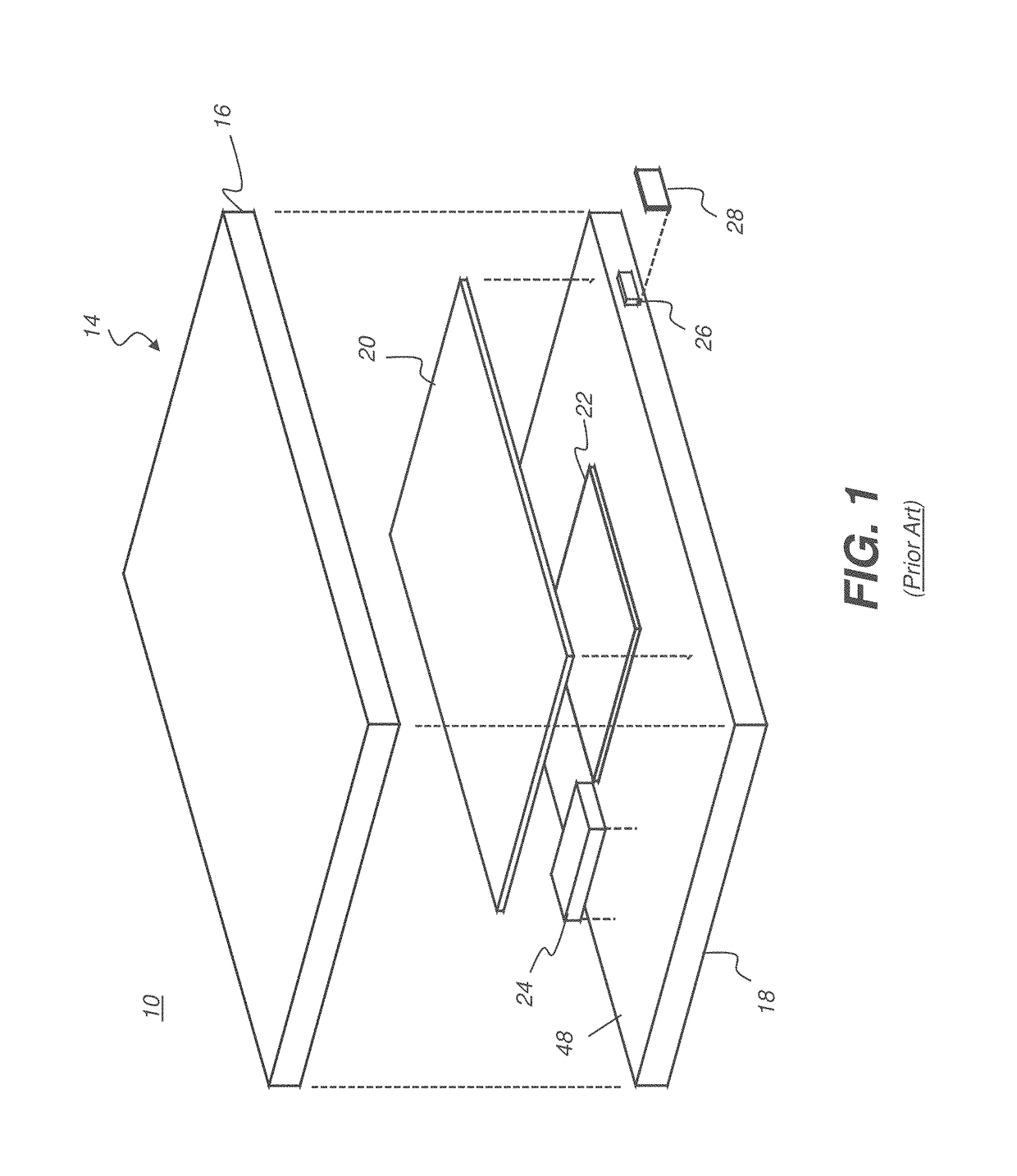
[0016]FIG. 1 is an exploded view that shows some of the components of a digital radiography (DR) detector.

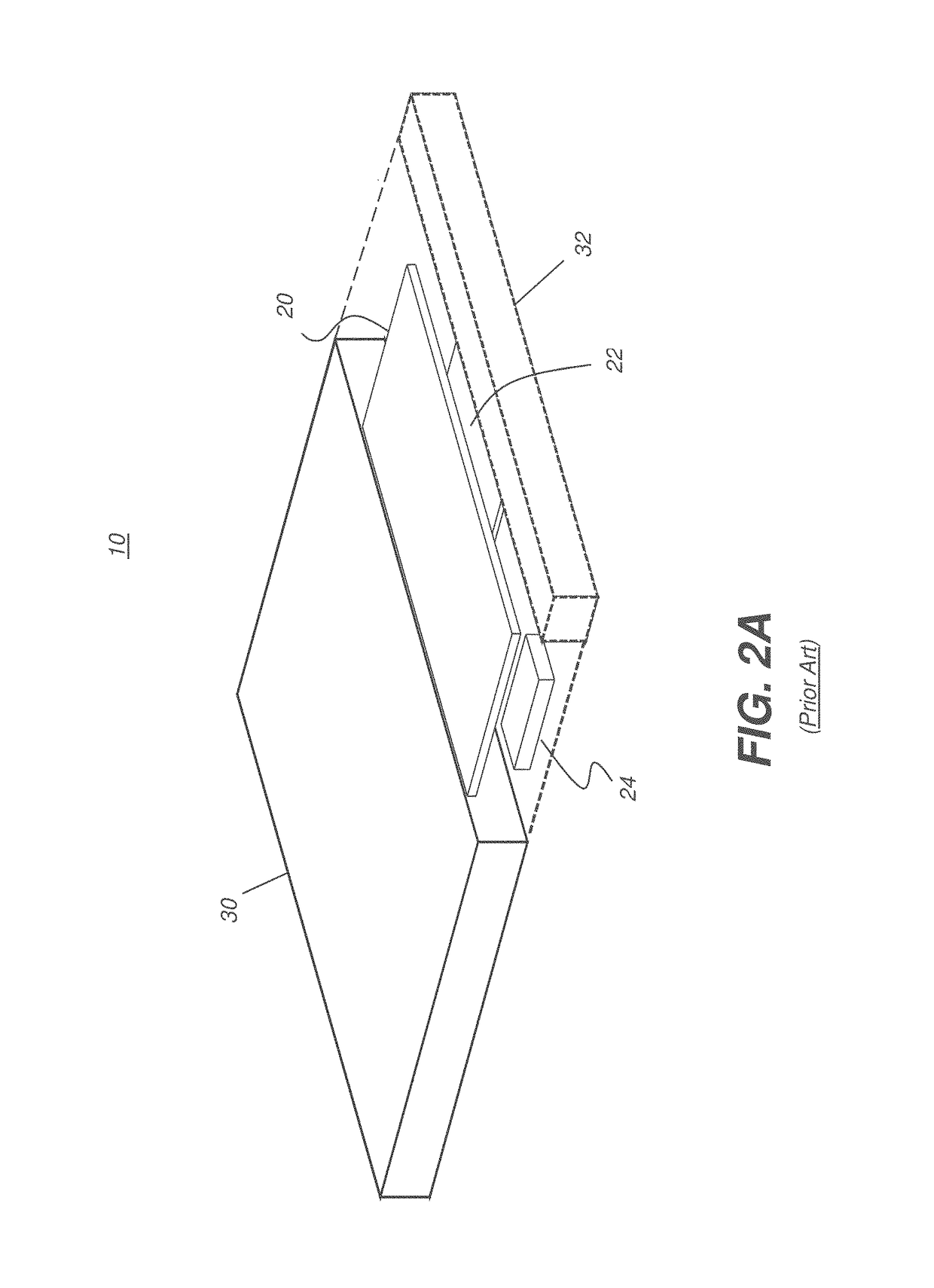
[0017]FIG. 2A is an exploded view that shows an alternate embodiment for DR detector packaging.

[0018]FIG. 2B shows a type of recording apparatus...


PUM


Abstract

A curved radiographic detector has electromagnetic radiation sensitive elements disposed in a two-dimensional array. A curved housing encloses the two-dimensional array of radiation sensitive elements and includes a layer of aligned carbon nanotubes on a surface thereof.

Description

CROSS REFERENCE TO RELATED APPLICATIONS[0001]This patent application is a continuation-in-part of U.S. patent application Ser. No. 14 / 811,871, filed Jul. 29, 2015, in the name of MacLaughlin, and entitled USE OF VERTICALLY ALIGNED CARBON NANOTUBE ARRAYS FOR IMPROVED X-RAY IMAGING DETECTOR PERFORMANCE.FIELD OF THE INVENTION[0002]The invention relates generally to the field of medical imaging and more particularly relates to apparatus and methods for treating an x-ray detector to reduce scattering of electromagnetic x-ray radiation.BACKGROUND[0003]Computed radiography (CR) and digital radiography (DR) imaging processes provide image content by converting received short wavelength x-ray energy to photoluminescent energy at higher spectral wavelengths, such as visible light energy. In CR, the energy from x-ray radiation is stored temporarily in a photostimulable storage phosphor medium for later release under an excitation light source and reading by an array of photodetectors. In DR, t...

Claims


Application Information

Patent Timeline
Patent Type & Authority Patents(United States)
IPC IPC(8): G01T7/00G01T1/164G01T1/24G21K1/10G01T1/20
CPCG21K1/10G01T1/1648G01T7/00G01T1/2018G01T1/247G01T1/2002G01T1/20183
Inventor MACLAUGHLIN, SCOTT T.
Owner CARESTREAM HEALTH INC
Why Eureka
Try Eureka