Antireflection film and method of producing the same

a technology of anti-reflection film and anti-reflection film, which is applied in the field of anti-reflection film, can solve the problems that the quality of optical elements is significantly affected by light in some cases, and achieve the effect of suppressing scattered ligh

Active Publication Date: 2019-12-31
FUJIFILM CORP
View PDF39 Cites 2 Cited by
  • Summary
  • Abstract
  • Description
  • Claims
  • Application Information

AI Technical Summary

Benefits of technology

[0013]According to the present invention, it is possible to provide an antireflection film capable of suppressing scattered light and a method of producing the same.

Problems solved by technology

While having conducted more intensive investigations on an antireflection structure including an uneven structure layer, the present inventors have found that when an antireflection structure includes an uneven structure layer made of an alumina hydrate, there is a problem in that slight scattering light at an unignorable level is generated and recognized as a cloud on an antireflection film forming surface in a product such as a lens so that the quality of an optical element is significantly affected by the light in some cases.

Method used


Image

  • Antireflection film and method of producing the same
  • Antireflection film and method of producing the same
  • Antireflection film and method of producing the same

Examples


first embodiment

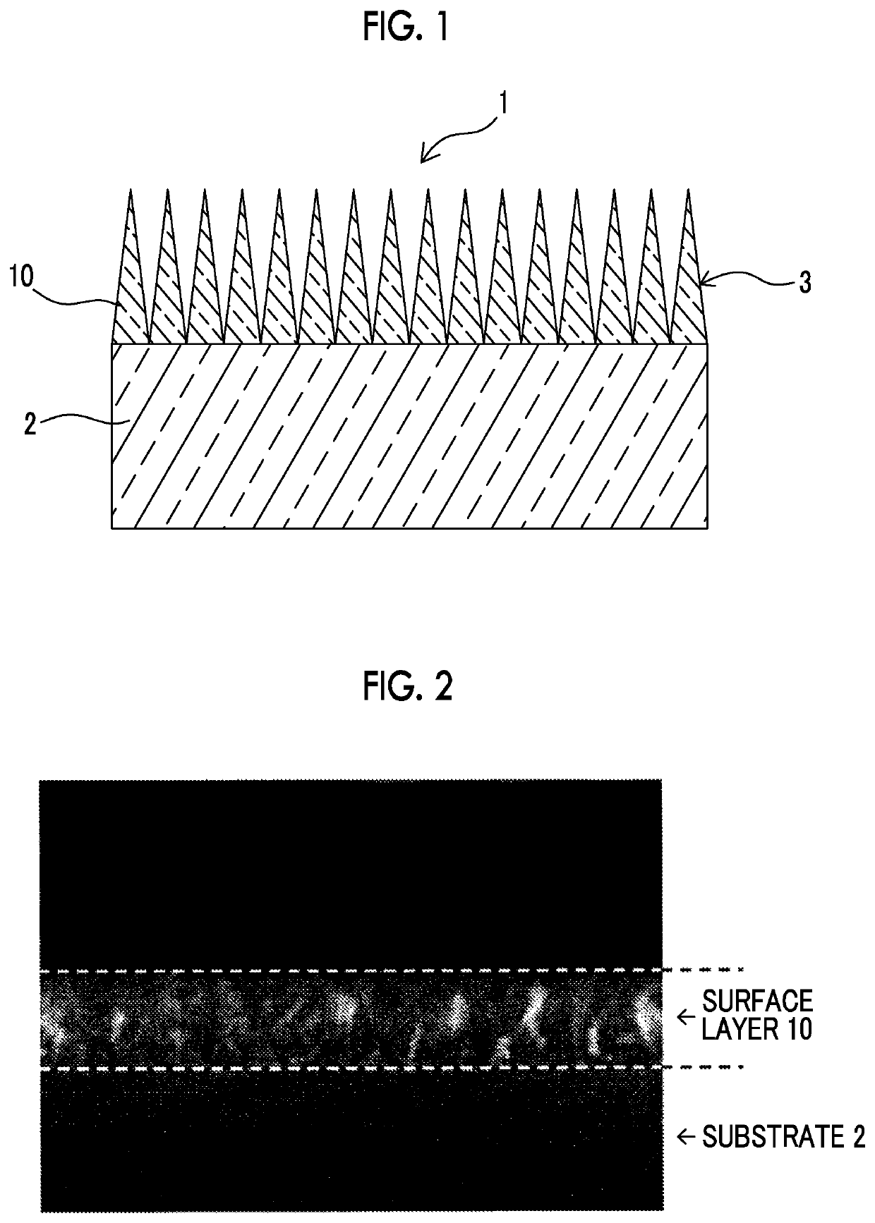
[0028]FIG. 1 is a schematic cross-sectional view showing a schematic constitution of an optical member provided with an antireflection film according to a first embodiment of the present invention. In addition, FIG. 2 is an electron microscope image obtained by imaging a cross section of the optical member provided with the antireflection film according to the first embodiment of the present invention in an enlarged manner.

[0029]As shown in FIGS. 1 and 2, an optical member 1 of the first embodiment includes a transparent substrate 2, and an antireflection film 3 that is formed on a surface of the substrate 2. The antireflection film 3 includes a transparent surface layer 10 having an alumina hydrate as a main component, and the surface layer 10 has an uneven structure in which a volume proportion of the alumina hydrate per unit volume decreases in a direction from the substrate 2 side to the surface side. In the surface layer 10, a period of apexes distributed on the surface side is...

second embodiment

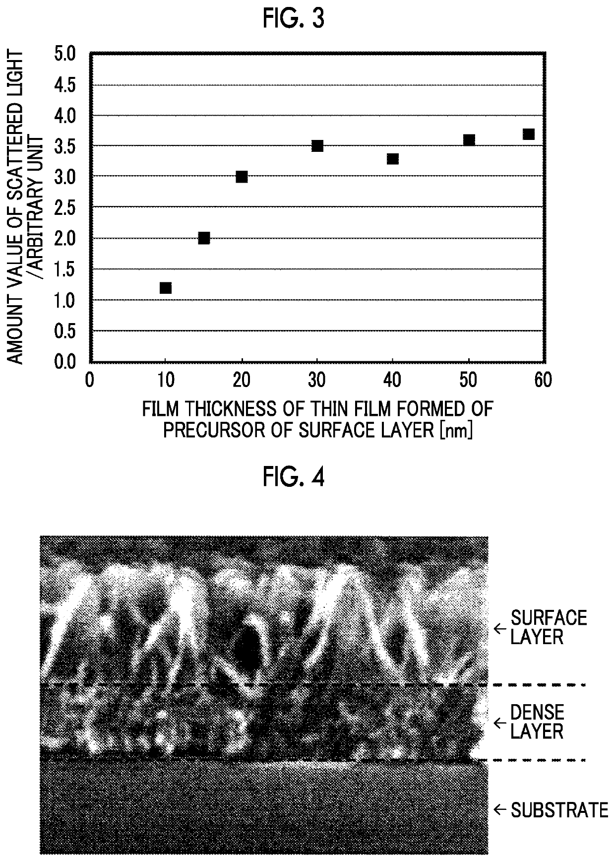
[0038]In the antireflection film 3 of the first embodiment, scattered light is suppressed because a dense layer is not formed. However, in the case in which a reliability test such as a temperature cycle test is performed, peeling-off occurs at the interface between the surface layer 10 and the substrate due to a difference in thermal expansion coefficient between the surface layer 10 and the substrate 2 and changes in temperature during the test, and a layer of air is formed in the peeled-off portion. Thus, it has been newly found that the reflective properties of the antireflection film 3 deteriorate in some cases.

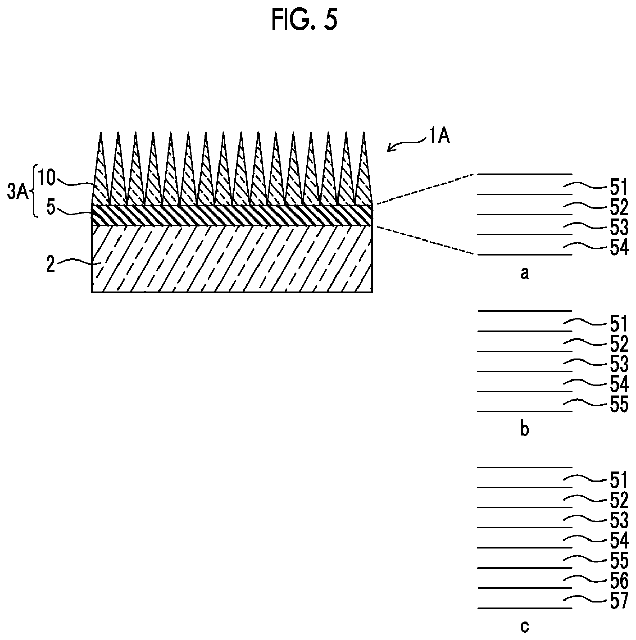
[0039]FIG. 5 is a schematic cross-sectional view showing a schematic constitution of an optical member provided with an antireflection film according to the second embodiment of the present invention. In addition, FIG. 6 is an electron microscope image obtained by imaging a cross section of the optical member provided with the antireflection film according to the second ...

example 1

[0056]A multilayer film in which layers of tantalum pentoxide (refractive index: 2.13755) as a high refractive index layer, and magnesium fluoride (refractive index: 1.38441) as a low refractive index layer were alternately laminated on a concave lens (curvature radius: 17 mm) made of FDS90 (manufactured by HOYA Corporation, refractive index: 1.8541) as a substrate included first to fourth layers. The thermal expansion coefficient value of the first layer formed of tantalum pentoxide as an adhesion layer is 9×10⁻⁶ / K at a reference temperature of 25° C. In the surface layer portion of the first layer, a thin aluminum film having a film thickness of 20 nm was formed as a precursor of the surface layer having an uneven structure. The refractive index of the surface layer having the uneven structure is changed from 1 to 1.27 from the air side to the substrate side. The layer constitution from the substrate to the thin aluminum film is as shown in Table 1 below.

[0057]In Table 1, the refr...


PUM

PropertyMeasurementUnit
refractive indexaaaaaaaaaa
thicknessaaaaaaaaaa
temperatureaaaaaaaaaa

Abstract

An antireflection film substrate that is provided on a surface of a substrate includes a surface layer having an alumina hydrate as a main component. The surface layer has an uneven structure in which a volume proportion of the alumina hydrate per unit volume decreases in a direction from the substrate side to a surface side, and a period of apexes distributed on the uneven structure on the surface side is configured to be equal to or less than a wavelength of light of which reflection is to be suppressed.

Description

CROSS REFERENCE TO RELATED APPLICATION(S)[0001]This is a continuation of International Application No. PCT / JP2016 / 060777 filed on Mar. 31, 2016, and claims priority from Japanese Patent Application No. 2015-072641 filed on Mar. 31, 2015, the entire disclosures of which are incorporated herein by reference.BACKGROUND OF THE INVENTION1. Field of the Invention[0002]The present invention relates to an antireflection film having an uneven structure on its surface and a method of producing the same.2. Description of the Related Art[0003]In the past, in a lens (transparent substrate) using a translucent member such as glass or plastic, an antireflection film has been provided on a light incident surface in order to reduce the loss of transmitted light by surface reflection.[0004]For example, as an antireflection structure for visible light, a dielectric material multilayer film, a fine uneven layer having a pitch shorter than a wavelength of visible light, and the like have been known (JP2...

Claims


Application Information

Patent Timeline
Patent Type & Authority Patents(United States)
IPC IPC(8): G02B1/118G02B1/115B32B9/04B32B37/14
CPCG02B1/118G02B1/115B32B9/04B32B37/14B32B2309/105B32B2307/418B32B9/00B32B3/30B32B7/12B32B15/04B32B15/08B32B2307/412B32B2307/40B32B2551/00
Inventor TAKAHASHI, HIROKI
Owner FUJIFILM CORP
Why Eureka
Try Eureka