Container sealing device

a sealing device and container technology, applied in the direction of closure using stoppers, liquid handling, applications, etc., can solve the problems of difficult to remove the upper closure and the like from the die, and achieve the effect of facilitating the separation of the separation par

Active Publication Date: 2018-10-02
TOKAN KOGYO CO LTD
View PDF36 Cites 27 Cited by
  • Summary
  • Abstract
  • Description
  • Claims
  • Application Information

AI Technical Summary

Benefits of technology

[0009]In the aforementioned container sealing device, the separation part or the inner plug is assembled in advance to the upper closure by using the second screwing part. At this time, since the assembling interval between the separation part and the upper closure can be adjusted by the first stopper, the second screwing part can be brought into a lock state of being screwed to the deepest position or a state close to that. Sealing of the sealing device becomes possible by pushing in or screwing the upper closure to the container or the inner plug. In opening the plug, the upper closure is rotated in a direction of being loosened with respect to the container. Namely, the first screwing part is loosened by rotating the upper closure so as to be screwed back, but along with that, the second screwing part which has been already substantially locked is tightened, and rapid and reliable separation of the separation part from the body part of the inner plug is facilitated. Therefore, after separation, that is, after opening the plug, the separation part becomes less likely to be removed from the upper closure, and is reliably held. As described above, a clear opening feeling such as generation of a snap sound or sudden reduction in resistance against rotation can be presented by separating the separation part from the body part of the inner plug while tightening the second screwing part which has been substantially locked. Note that the separation part is considered to be fixed to the support part in advance by causing the second screwing part to have a mere fitting structure of irregularity, but an undercut part required to be provided in a molding die for the upper closure and the like, and it becomes difficult to withdraw the upper closure and the like from the die. On the other hand, it becomes no longer necessary to provide the undercut part in the molding die by adoption of a thread shape as a method of fixing the separation part and the support part as in the second screwing part, and the difficulty in the process of withdrawing the upper closure and the like from the die can be overcome extremely easily.
[0014]In still another viewpoint of the present invention, the first stopper is provided at least at either one of a lower end of the first inner cylinder part provided at the support part and an upper end of the cylindrical part extending upward from the sealing body provided on the separation part. In this case, an assembling interval between the upper closure and the body part can be accurately adjusted by length adjustment in an axial center direction of the first inner cylinder part or the cylindrical part. Moreover, support of the separation part is made stable, and a sealing function can also be given to the first stopper.
[0015]In still another viewpoint of the present invention, a second stopper regulating the mutual assembling interval is provided between the upper closure and the body part of the inner plug. In this case, when the inner plug is assembled to the upper closure or the upper closure is attached to the container or the inner plug, excessive pushing-in of the body part into the upper closure can be prevented, and occurrence of damage to the separation part can be reliably prevented.
[0016]In still another viewpoint of the present invention, the second stopper is provided at a lower end of a second inner cylinder part provided on the upper closure. In this case, the assembling interval between the upper closure and the body part can be accurately adjusted by length adjustment in an axial center direction of the second inner cylinder part.
[0018]In still another viewpoint of the present invention, a score is provided between the body part of the inner plug and the separation part. In this case, sealing of the inner plug by the separation part is made reliable, and separation of the separation part is also facilitated.

Problems solved by technology

Note that the separation part is considered to be fixed to the support part in advance by causing the second screwing part to have a mere fitting structure of irregularity, but an undercut part required to be provided in a molding die for the upper closure and the like, and it becomes difficult to withdraw the upper closure and the like from the die.

Method used


Image

  • Container sealing device
  • Container sealing device
  • Container sealing device

Examples


Embodiment Construction

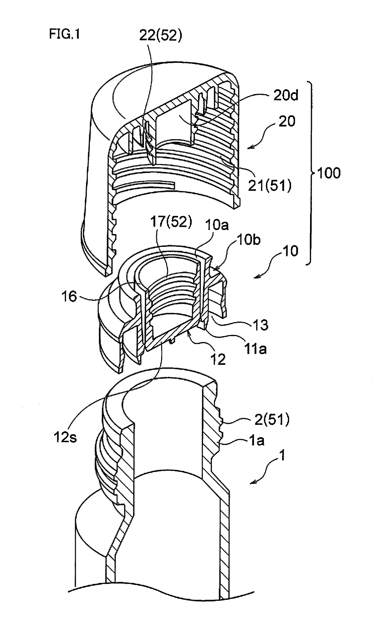
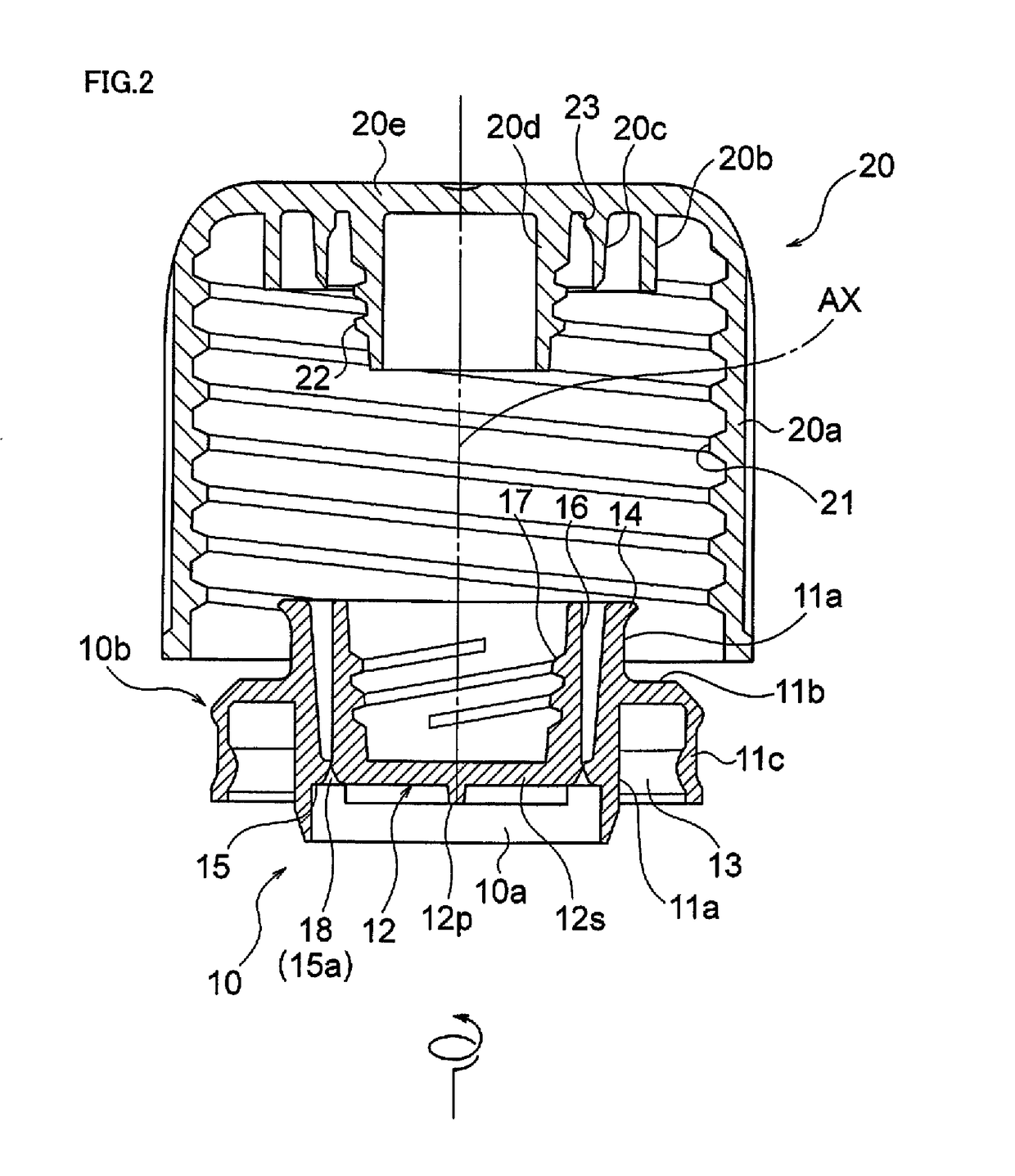
[0025]FIGS. 1 to 5 illustrate an embodiment of a container sealing device according to the present invention.

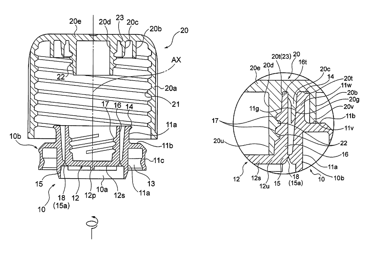
[0026]An illustrated sealing device 100 is constituted of an inner plug 10 locked by a mouth part 1a of a container 1 through fitting or the like, and an upper closure 20 screwed with the mouth part 1a of the container 1 so as to cover an extraction port 10a of the inner plug 10.

[0027]The inner plug 10 is an integrally molded product made of a resin and is provided with a body part 10b locked by or fixed to the container 1 and a separation part 12.

[0028]As illustrated in FIG. 2 and the like, the body part 10b of the inner plug 10 forms the extraction port 10a of a content of the container 1 and has a cylindrical base part 11a which is a cylindrical member extending along an axial center AX, a flange part 11b extending outward in a radial direction from an outer peripheral surface of an intermediate part of the cylindrical base part 11a, and an annular wall part 11c which is a...


PUM


Abstract

An object is to provide a container sealing device which can perform an opening of an inner plug with a clear opening feeling. An inner plug 10 is assembled in advance to an upper closure 20 by using a second screwing part 52. At this time, since an assembling interval between a separation part 12 and the upper closure 20 can be adjusted by tip end parts 16t and 20u of a cylindrical part 16 which are first stoppers and the small-diameter cylinder part 20d, the second screwing part 52 can be brought into a lock state of being screwed to the deepest position or a state close to that. In opening the plug, the first screwing part 51 is loosened the second screwing part 52 is tightened, and the separation part 12 can be rapidly and reliably separated from a body part 10b of the inner plug 10.

Description

CROSS-REFERENCE TO RELATED APPLICATIONS[0001]This application is the U.S. National Phase under 35 U.S.C. § 371 of International Application PCT / JP2014 / 051577, filed Jan. 24, 2014, which claims priority to Japanese Patent Application No. JP 2013-012712, filed Jan. 25, 2013, the entirety of which is incorporated herein by reference.TECHNICAL FIELD[0002]The present invention relates to a container sealing device to be attached to a bottle-shaped container.BACKGROUND ART[0003]As a known cap structure (sealing device) used for a container with a closure, there is a structure which is provided with an inner plug and an upper closure, and in which a cylindrical part fitted with an opening part of a bottle and a separation part continuously provided on an inner side thereof via a score are provided in the inner plug (refer to FIGS. 1 and 2 in Patent Literature 1).[0004]In this cap structure, the upper closure is preliminarily engaged (screwed) with the separation part of the inner plug thro...

Claims


Application Information

Patent Timeline
Patent Type & Authority Patents(United States)
IPC IPC(8): B65D47/36B65D39/00B65D51/22B65D39/08B65D47/12B65D47/10
CPCB65D39/0052B65D39/08B65D47/106B65D51/228B65D47/123B65D2251/0087B65D2251/0015
Inventor ISOGAI, TAKAMITSU
Owner TOKAN KOGYO CO LTD
Why Eureka
Try Eureka