
Throttle device, and refrigeration cycle system including same

a technology of throttle device and refrigeration cycle, which is applied in the direction of functional valve types, lighting and heating apparatus, refrigeration components, etc., can solve the problems of failure to control the pressure of refrigerant in refrigeration, abnormal noise, etc., and achieve the effect of moderately increasing the aperture area of the valve port and stably controlling the flow rate of refrigeran

Active Publication Date: 2018-10-02
SAGINOMIYA SEISAKUSHO INC
View PDF23 Cites 0 Cited by
  • Summary
  • Abstract
  • Description
  • Claims
  • Application Information

AI Technical Summary

Benefits of technology

The present invention provides a throttle device and refrigeration cycle system that can prevent a hunting phenomenon of a valve body and control the flow rate of refrigerant stably. This is achieved by ensuring the maximum insertion length of the needle member into the valve port is equal to or above a specific value. The result is an increase in the aperture area of the valve port, which prevents the hunting phenomenon and stabilizes the flow rate of the refrigerant.

Problems solved by technology

Hereby, this phenomenon may lead to abnormal noise and a failure in controlling the pressure of the refrigerant in the refrigeration system to a predetermined target pressure.

Method used


Image

  • Throttle device, and refrigeration cycle system including same
  • Throttle device, and refrigeration cycle system including same
  • Throttle device, and refrigeration cycle system including same

Examples


first embodiment

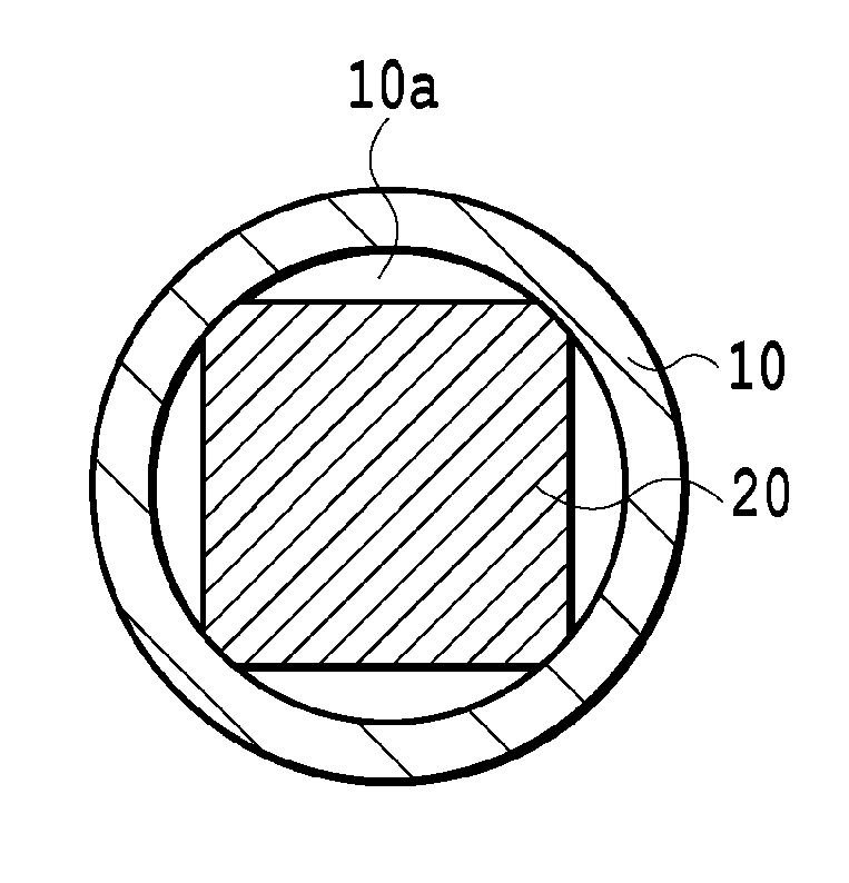
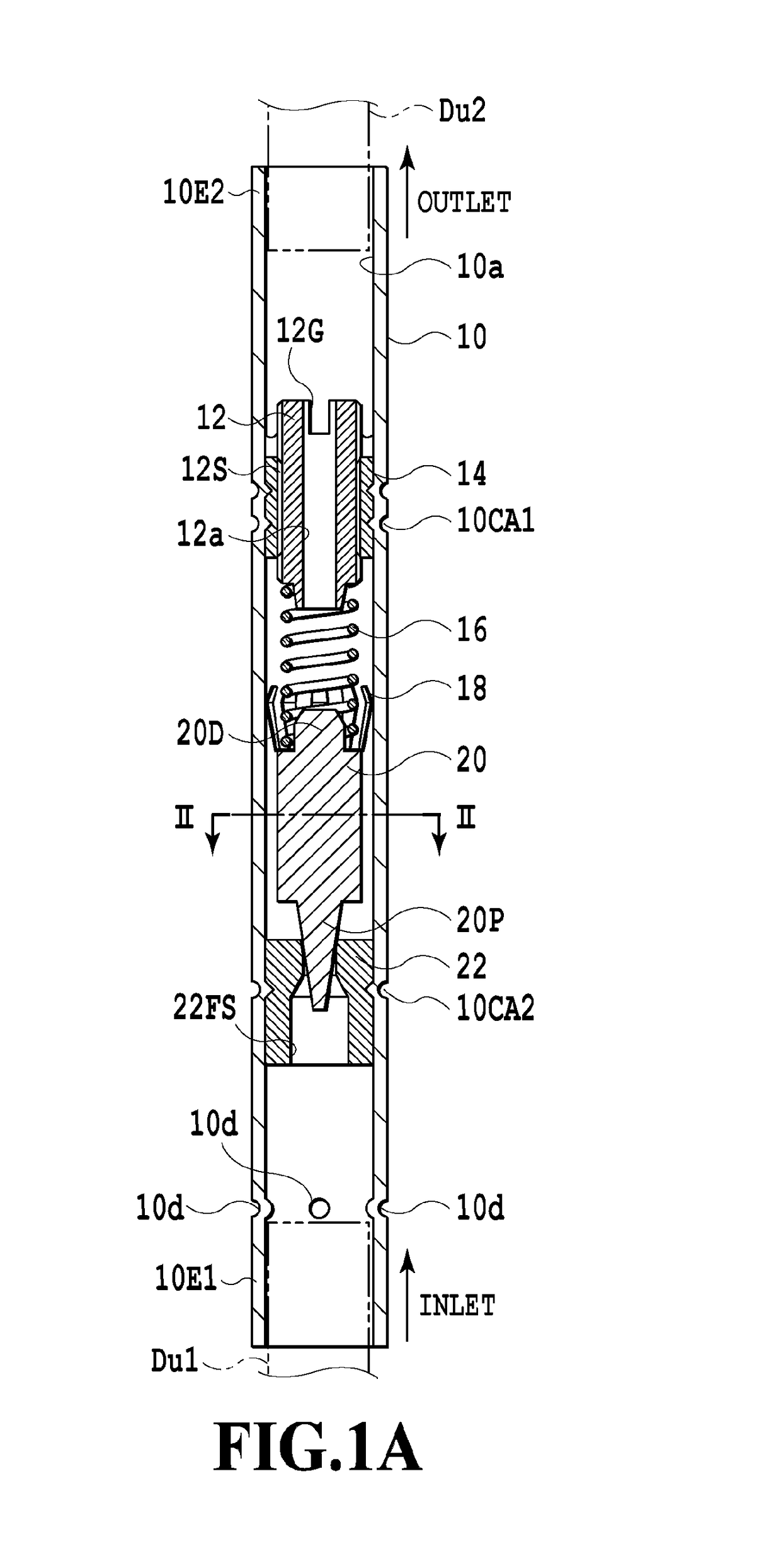
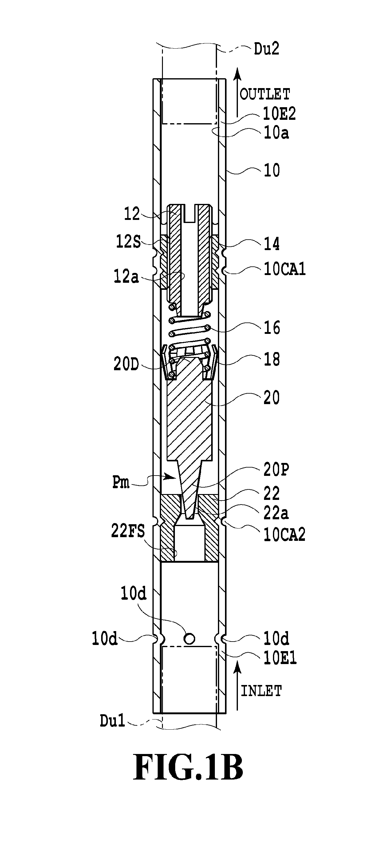
[0029]Each of FIG. 1A and FIG. 1B shows a configuration of a throttle device according to the present invention.

[0030]As schematically shown in FIG. 3, for example, the throttle device is disposed between an outlet of a condenser 6 and an inlet of an evaporator 2 in a ductwork of a refrigeration cycle system. The throttle device is coupled to a primary duct Du1 at one end 10E1 of a tube body 10 to be described later, and is coupled to a secondary duct Du2 at another end 10E2 of the tube body 10 from which a refrigerant is discharged. The primary duct Du1 connects the outlet of the condenser 6 to the throttle device while the secondary duct Du2 connects the inlet of the evaporator 2 to the throttle device. As shown in FIG. 3, a compressor 4 is connected between an outlet of the evaporator 2 and an inlet of the condenser 6 by using a duct Du3 to be coupled to the outlet of the evaporator 2 and a duct Du4 to be coupled to the inlet of the condenser 6. The drive of the compressor 4 is c...

second embodiment

[0056]FIG. 8 shows a configuration of a throttle device according to the present invention.

[0057]In the example shown in FIG. 8, a valve seat 32 is provided with a valve support 32a, and moreover, a bypass 32PT serving as a communication passage that establishes communication between a cylindrical portion to be described later and a portion to house the needle member 20. Note that in FIG. 8, the same constituents as those in FIG. 1A will be denoted by the same reference signs and overlapping description thereof will be omitted.

[0058]As schematically shown in FIG. 3, for instance, the throttle device is disposed between the outlet of the condenser 6 and the inlet of the evaporator 2 in the ductwork of the refrigeration cycle system as with the example shown in FIG. 1A.

[0059]The throttle device comprises, as its main elements: the tube body 10 coupled to the ductwork of the above-mentioned refrigeration cycle system; the valve seat 32 fixed to the inner peripheral portion of the tube ...


PUM


Abstract

In a throttle device, a needle member (20) includes a tapered portion (20P) having a taper angle (2θ), and a length (X) along a center axis from a position (20PS) to an apical surface of the tapered portion (20P) is set to a value equal to or above a prescribed amount of lift (L′×cos2 θ), where the position (20PS) is a position corresponding to an edge (22as) of a valve port (22a) in a state where the tapered portion (20P) is inserted in the valve port (22a) and establishes a closed state of the valve port (22a).

Description

TECHNICAL FIELD[0001]The present invention relates to a throttle device, and a refrigeration cycle system including the same.BACKGROUND ART[0002]In the field of refrigeration systems in air-conditioning apparatuses, there has been proposed one including a differential pressure-type throttle device instead of a capillary tube serving as the throttle device. For example, a differential pressure-type throttle device like those disclosed in patent document 1 to patent document 4 is configured to optimally control a pressure of a refrigerant between an outlet of a condenser and an inlet of an evaporator in order to efficiently operate a compressor in accordance with an outside air temperature. Moreover, in a refrigeration system capable of changing the number of revolutions of the compressor, the differential pressure-type throttle device is also configured to optimally control the pressure of the refrigerant according on the number of revolutions of the compressor from the labor saving ...

Claims


Application Information

Patent Timeline
Patent Type & Authority Patents(United States)
IPC IPC(8): F25B41/06F16K17/30F16K1/34F16K1/38F16K1/54F16K15/02F16K17/04
CPCF25B41/062F16K1/34F16K1/38F16K15/026F16K17/0466F16K17/30F16K1/54F25B2500/15F25B41/33
Inventor TAKADA, YASUMASATOYAMA, YUICHIRO
Owner SAGINOMIYA SEISAKUSHO INC
Learn More