Electrosurgical instrument and jaw part therefor

a surgical instrument and electrode technology, applied in the field of electrosurgical instruments, can solve the problems of inability to stably maintain the closed position of the leg spacing, risk that such non-conductive, nub-shaped protrusions can easily break off in use, and remain unnoticed, so as to achieve the effect of preventing coagulation shadows and gripping more reliably

Active Publication Date: 2018-10-09
AESCULAP AG
View PDF88 Cites 139 Cited by
  • Summary
  • Abstract
  • Description
  • Claims
  • Application Information

AI Technical Summary

Benefits of technology

[0015]The present invention is based on the new knowledge briefly indicated above, which says that spacers which are immediately arranged on the electrode areas or fixed thereon and necessarily must be made hitherto from an electrically non-conductive material, locally limit / impede the flow of electrical current into the clamped tissue, so that a continuous tissue weld seam is not ensured. In order to reduce these negative effects, it would be basically possible to implement the spacers as small as possible, e.g. with the shape of a mandrel or needle. However, it has turned out that spacers formed in such a way do not withstand the clamping forces between the legs and hence are not able to stably maintain the leg spacing in the closed position. What is more, there is the risk that such non-conductive, nub-shaped protrusions can easily break off in use, and then remain unnoticed in the tissue of a patient for instance during an operation. For this reason, the present invention basically suggests to manufacture the preferably nub-shaped spacers made of an electrically conductive material and directly arranged on the electrode areas or fixed thereon e.g. such that they are formed integrally with or soldered / welded to the corresponding electrode, and instead to provide non-conductive spacer abutment surfaces on the respectively opposing electrode, on which the electrically conductive spacers will come to rest. As the electrically non-conductive spacer abutment surfaces, for instance in the form of glued, applied, inserted or poured-in pads / platelets / pins are substantially level with the electrode area, i.e. have none or only a small protruding portion with respect to the corresponding electrode area, they can not be detached / torn off from the electrode area or only with difficulty. Accordingly, each of the spacer abutment surfaces can be realized with a smaller size regarding the areal dimensions compared to electrically non-conductive spacers known hitherto, as the spacer abutment surfaces do not have to introduce any shear forces into the electrode which is due to the small or missing protruding portion. The spacers themselves may consist of a material such as metal which withstands high shear forces, so that they can be dimensioned in small size, too. As a whole, this contributes to avoid coagulation shadows and at the same time to improve the functional reliability.
[0036]As this ridge is smaller than the minimum distance of the two instrument legs which is defined by the spacer in the closed position, e.g. 10% to 75% of the distance, these will never come to rest against the opposing instrument leg. This is why the tissue between the ridge and the opposing instrument leg is not perforated and hence not permanently damaged. Further, these ridges do also not cause any coagulation shadows, as the tissue clamped between the ridge and the opposing instrument leg is not covered to a substantial extent. In this way, the coagulation shadows are prevented, which occur when conventional instruments are used. As these ridges do not come into contact with the opposing instrument leg anyway, they too may be made of an electrically conductive material; in this case, opposing pads / pins of electrically non-conductive material may be dispensed with. It is possible, of course, to provide several of such ridges for each electrode area. They can be arranged at regular intervals.

Problems solved by technology

However, it has turned out that spacers formed in such a way do not withstand the clamping forces between the legs and hence are not able to stably maintain the leg spacing in the closed position.
What is more, there is the risk that such non-conductive, nub-shaped protrusions can easily break off in use, and then remain unnoticed in the tissue of a patient for instance during an operation.

Method used


Image

  • Electrosurgical instrument and jaw part therefor
  • Electrosurgical instrument and jaw part therefor
  • Electrosurgical instrument and jaw part therefor

Examples


first embodiment

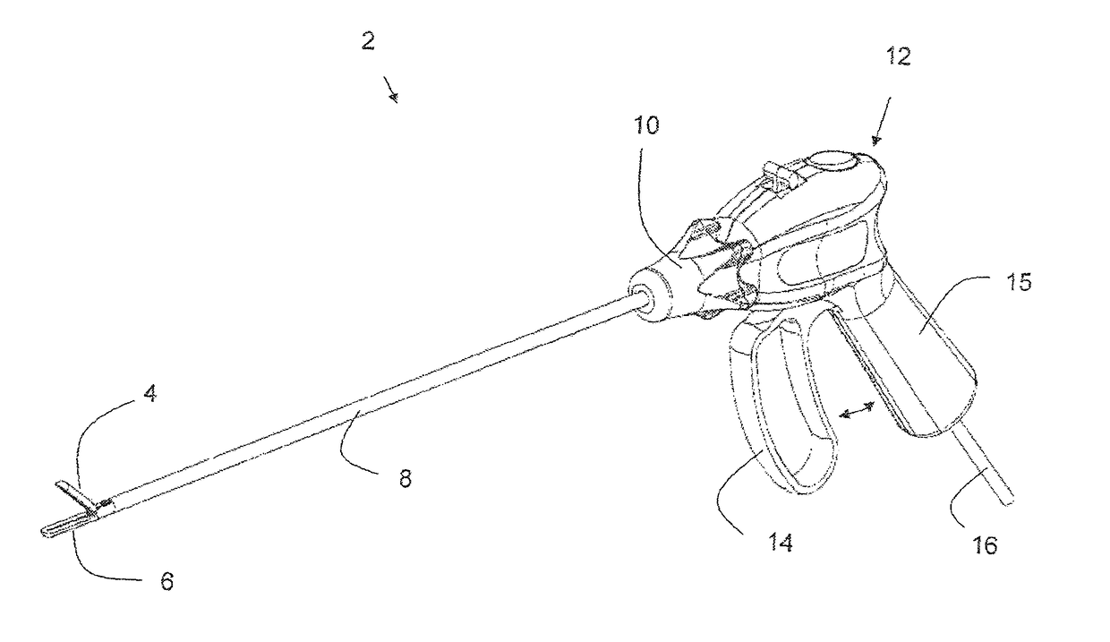
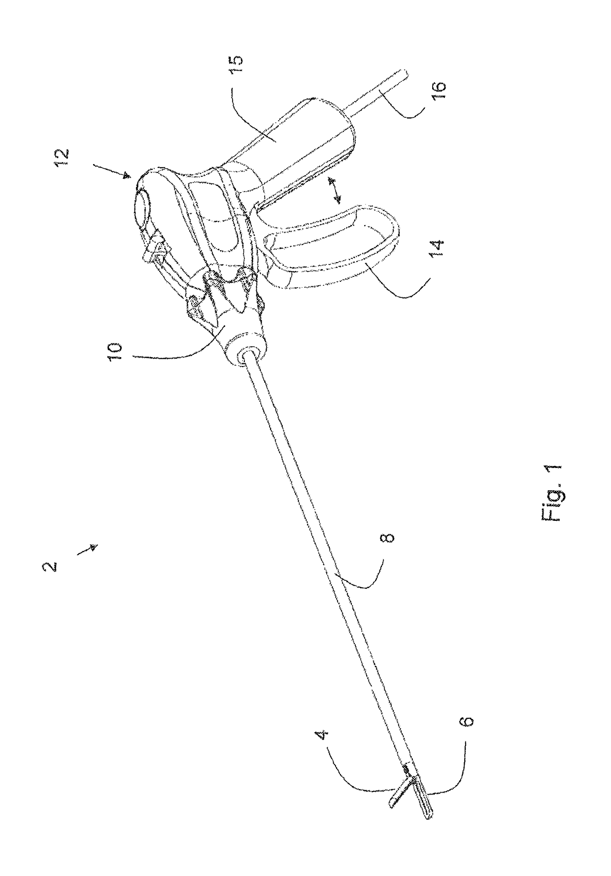
[0059]FIG. 1 shows a perspective view of a laparoscopic electrosurgical instrument 2 in open position according to the invention, comprising a jaw part consisting of a pair of instrument legs 4 and 6, which move relative to each other preferably in the manner of scissors or tongs, and are arranged on the distal end of an instrument shaft 8 which for its part is rotatably fastened to a handle piece or manipulation part 12 via a manually operable shaft rotation device 10. The shaft rotation device 10 allows to rotate the shaft 8 (and the instrument legs 4 and 6 arranged thereon) relative to the manipulation part 12 about the longitudinal axis of the shaft. The manipulation part 12 comprises a manually operable handle or trigger guard 14 which is able to move in pivoting manner relative to a handle or pistol grip 15 firmly connected to the manipulation part 12. The instrument legs 4, 6 or at least one manually operable instrument leg 4 are / is in operative connection with the handle 14 ...

second embodiment

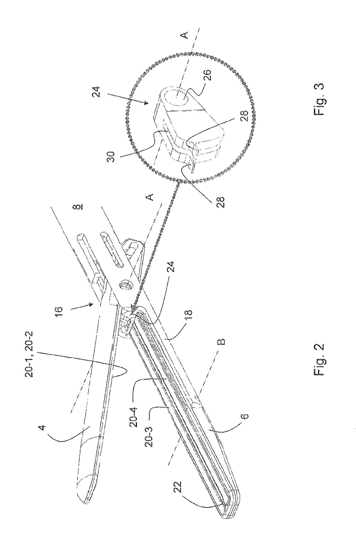
[0070]In the second embodiment, two (nub-shaped) protrusions 32, 34 are immediately provided (i.e. firmly fixed) on the distal end portions of the electrode areas 20-3 and 20-4, instead of the protrusion 22 arranged between the electrode areas 20-3 and 20-4. In order to avoid a short-circuit between the electrode areas if these approach the electrode areas of the upper instrument leg 4 in the closed position, the protrusions 32, 34 are manufactured from an electrically conductive material and come to rest against a spacer abutment surface made of a non-conductive material which is provided on the respectively other of the opposing electrodes (exclusively) in the region of the respective protrusion (point- / pad-shaped). The protrusions 32, 34 may be applied by soldering or injection-molding or can be formed integrally (such as by embossing or stamping). The spacer abutment surface can be formed by injection-molding, spreading or filling in a hardening mass or by gluing or inserting an...

seventh embodiment

[0077]FIG. 17 shows an electrosurgical instrument 102 which differs from the instrument 2 described above in terms of the instrument type, in particular with regard to the construction of the operating device as well as the handle. Whereas all of the various embodiments described above have been described with reference to the laparoscopic electrosurgical instrument 2 illustrated in FIG. 1 comprising a thin, long shaft 12 and instrument legs 4 and 6 pivotally articulated thereon as a distal jaw part, the variants of the spacer arrangement which have been described above can also be realized in connection with the instrument 102 in which, however, two instrument legs 104 and 106 are connected to each other via a slide element 108 and a corresponding operation mechanism (not shown in further detail). With this arrangement, the handle or handle piece comprises a kind of accommodation duct from which the instrument legs protrude in axial as well as distal manner. This duct is dimension...


PUM


Abstract

An electrosurgical instrument including a jaw part made up of mutually movable instrument legs which have facing sides on which one or more electrode areas are arranged / formed in each case, the movement of the instrument legs relative to each other being able to be limited by at least one first spacer acting on proximal end portions of the instrument legs and at least one second spacer acting on distal end portions of the instrument legs. At least one of the spacers on at least one electrode is manufactured from an electrically conductive material and is connected to the electrode in electroconductive fashion. Furthermore, the spacer cooperates with a local spacer abutment surface which is made of a non-conductive material and arranged in electrically insulating manner on at least one opposing electrode.

Description

CROSS-REFERENCE TO RELATED APPLICATIONS[0001]This application is the U.S. National Phase patent application of International PCT Application No. PCT / EP2012 / 076945, filed Dec. 27, 2012, which claims the benefit of priority of German Application No. 10 2012 100 040.9, filed Jan. 4, 2012, the contents of both applications being incorporated by reference herein in their entirety.FIELD OF THE INVENTION[0002]The present invention relates to an electrosurgical instrument, in particular for laparoscopic operations.BACKGROUND OF THE INVENTION[0003]Following the surgical removal of a hollow vessel portion, e.g. with an intestinal resection due to a tumor having affected a bowel section, the two hollow vessel portions have to be reconnected at their opened ends in such a manner that a continuous pathway is produced. This is referred to as end-to-end anastomosis. As a standard, the two opened ends are reattached to each other with clip suturing devices.[0004]In particular with operations on the...

Claims


Application Information

Patent Timeline
Patent Type & Authority Patents(United States)
IPC IPC(8): A61B18/14A61B18/00A61B90/00
CPCA61B18/1445A61B18/1442A61B2090/033A61B2018/00083A61B2018/00494A61B2018/0016
Inventor ROTHWEILER, CHRISTOPHHERNER, EUGENHUBER, CHRISTIAN
Owner AESCULAP AG
Why Eureka
Try Eureka