Method of forming a carbon fiber layup

a carbon fiber and layup technology, applied in the field of carbon fiber layup forming methods and systems, can solve the problems of reducing the strength of the oven or autoclave, affecting the integrity of the final build, and requiring significant power in the oven, so as to improve the strength and reduce the size and temperature constraints, the effect of increasing the stiffness

Active Publication Date: 2018-10-09
UT BATTELLE LLC
View PDF6 Cites 2 Cited by
  • Summary
  • Abstract
  • Description
  • Claims
  • Application Information

AI Technical Summary

Benefits of technology

[0009]Development of new materials, extrusion and deposition technologies that enable “oven-less” advanced manufacturing and carbon fiber layup in a single location, within a single work area, and at room or ambient temperatures will provide significant advancement in the state of the art, removing size and temperature constraints from future advanced manufacturing systems. One focus of this invention is the use of carbon fiber reinforcements and layup of a component to aid in structural stability, increased strength and increased stiffness.
[0011]As described, polymers may be used in advanced manufacturing to construct a mandrel over which a carbon fiber layup may be positioned, in place and in continuation of the process, on preferably the same equipment as the mandrel. The mandrel can then be removed resulting in a composite part, without the need for movement or transfer of the mandrel to a further layup stage or the requirement of an oven or a heated bed, thus allowing for large scale part production that maintains the integrity of the build and reduces energy usage.

Problems solved by technology

On the contrary, rapid prototyping processes typically produce exemplary models that are not production ready.
In addition, both processes may require movement of the part in process from buildup to curing to layup, thus endangering the integrity of the final build.
In addition, the utilization of an oven or autoclave introduces many limitations.
First, the oven requires significant power, especially for higher temperature and larger parts.
If materials change, it also takes time to get the oven up to the proper operating temperature.
Temperature gradients within the oven introduce distortions and dimensional variability in parts as well.
Another constraint introduced by the oven, autoclave or heated bed is a limitation on the build envelope size.
As such, the resulting builds must fit within this envelope or be constructed in assembled stages thereby increasing complexity and cost and limiting strength and engineering flexibility.

Method used


Image

  • Method of forming a carbon fiber layup
  • Method of forming a carbon fiber layup
  • Method of forming a carbon fiber layup

Examples


Embodiment Construction

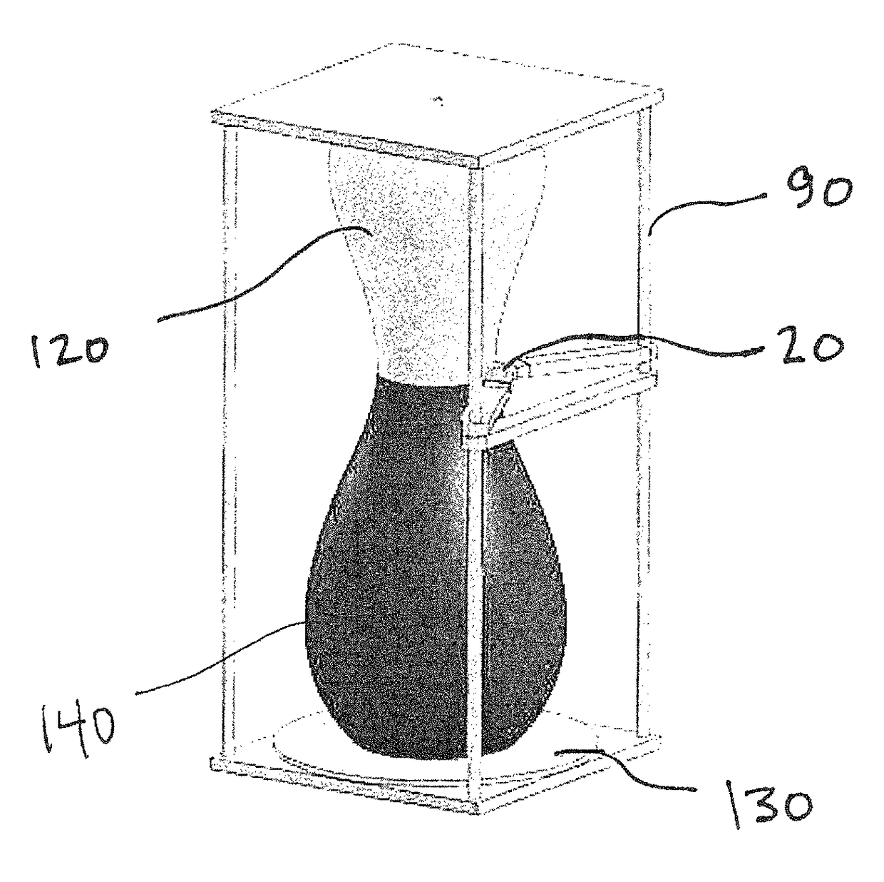
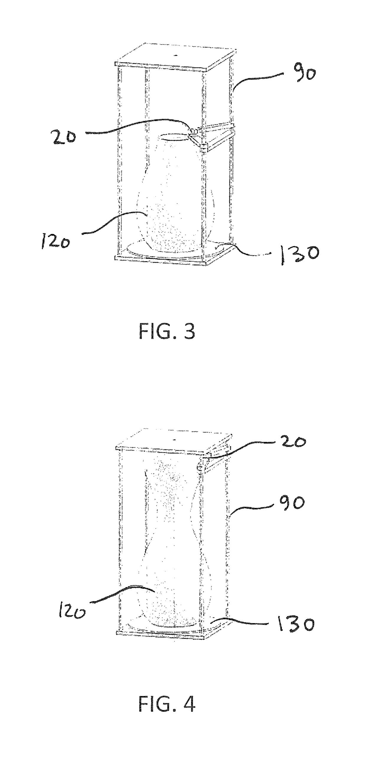
[0018]The present invention provides a component manufactured using an advanced manufacturing process wherein a supply of working material including a carbon-fiber reinforced polymer is provided to a deposition system. The working material is then deposited in a desired position through a nozzle during a build of the component. “Component” as used herein refers to either or both of a mandrel and then a carbon fiber layup on the mandrel to form the component. As used herein, “mandrel” is intended to mean an object of any shape or configuration that is used to provide form to the carbon fiber layup and the resulting component. The build of the component preferably occurs at atmospheric temperature and outside of the confines or limitations of an oven, heated bed or similar system.

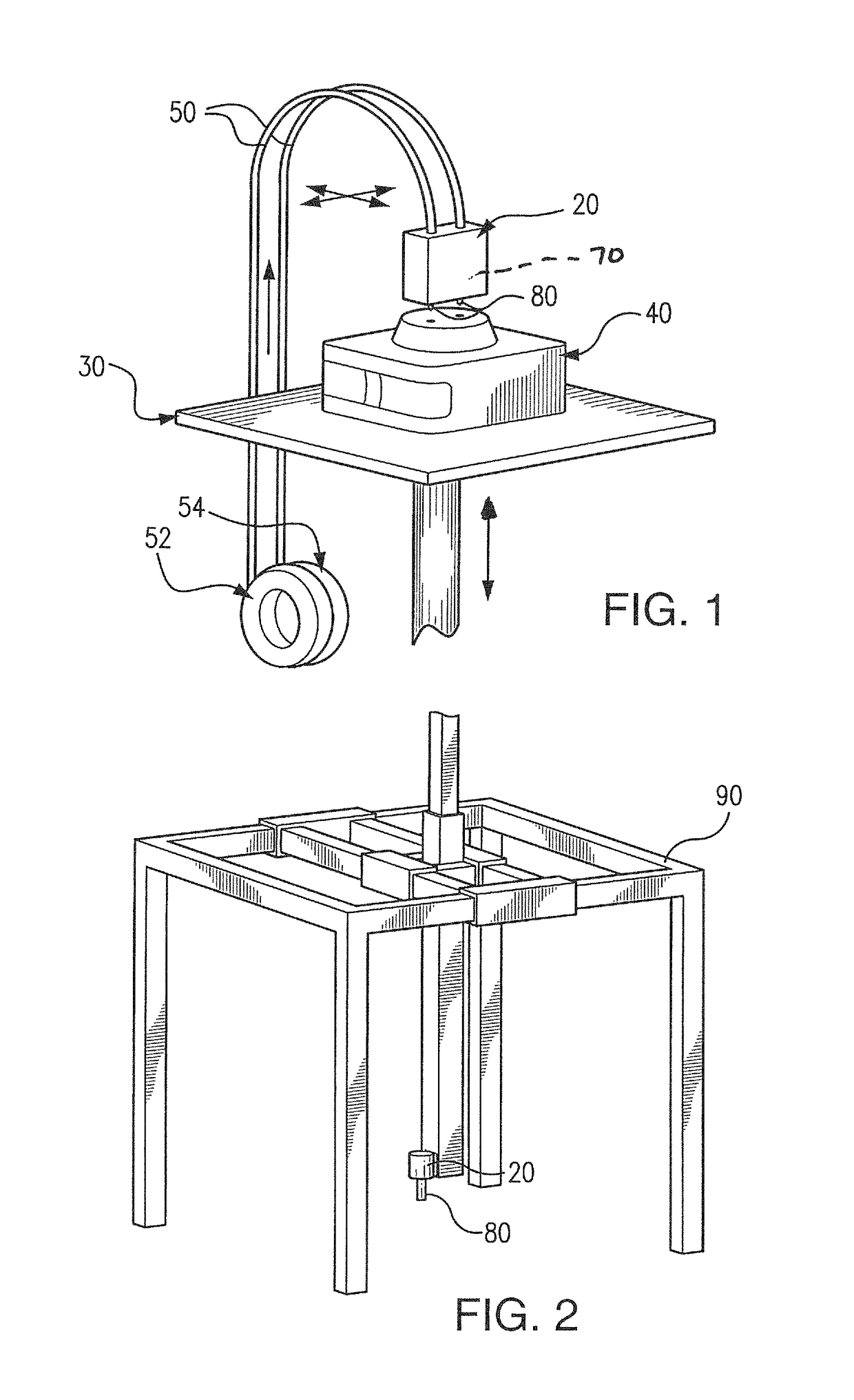
[0019]Polymer extrusion systems feed a polymer filament into a liquefier to extrude a material, such as shown in FIG. 1. Polymer extrusion systems typically use a moveable print head 20 positioned with respec...


PUM

PropertyMeasurementUnit
atmospheric temperatureaaaaaaaaaa
temperaturesaaaaaaaaaa

Abstract

A manufactured component, method and apparatus for advanced manufacturing that includes a polymeric working material formed into a mandrel with a carbon fiber overlay formed in a continuation of the process. The mandrel build and the carbon fiber overlay of the component preferably take place at atmospheric temperatures.

Description

GOVERNMENT RIGHTS[0001]This invention was made with government support under Contract No. DE-AC05-00OR22725 awarded by the U.S. Department of Energy. The government has certain rights in the invention.FIELD OF THE INVENTION[0002]The present invention relates to a method and system for forming a carbon fiber layup using large scale polymer additive manufacturing.BACKGROUND OF THE INVENTION[0003]Advanced manufacturing, also referred to as additive manufacturing, may be used to quickly and efficiently manufacture complex three-dimensional components layer-by-layer, effectively forming the complex component. Such advanced manufacturing may be accomplished using polymers, alloys, powders, solid wire or similar feed stock materials that transition from a liquid or granular state to a cured, solid component.[0004]Polymer-based advanced manufacturing is presently accomplished by several technologies that rely on feeding polymer materials through a nozzle that is precisely located over a pre...

Claims


Application Information

Patent Timeline
Patent Type & Authority Patents(United States)
IPC IPC(8): B29C70/38B29C67/00B29C33/44B29C33/52B33Y10/00B29K101/12
CPCB29C70/38B29C33/448B29C64/106B29C33/52B29K2101/12B33Y10/00B29C64/118
Inventor KUNC, VLASTIMILLIND, RANDALL F.LOVE, LONNIE J.
Owner UT BATTELLE LLC
Why Eureka
Try Eureka