All-fiber weak magnetic field measuring device

A technology of weak magnetic field and measuring device, which is applied in the direction of magnetic field measurement, magnetic field size/direction and other directions using magneto-optical equipment, can solve the problems of temperature cross sensitivity, low sensitivity, complex structure, etc., and achieve the elimination of polarization signal fading, The effect of high signal-to-noise ratio and simple processing technology

Inactive Publication Date: 2015-11-25
UNIV OF ELECTRONICS SCI & TECH OF CHINA
View PDF4 Cites 11 Cited by
  • Summary
  • Abstract
  • Description
  • Claims
  • Application Information

AI Technical Summary

Problems solved by technology

The optical fiber magnetic field sensor has good stability, but has disadvantages such as temperature cross-sensitivity, low sensitivity, and complex structure.

Method used


Image

  • All-fiber weak magnetic field measuring device
  • All-fiber weak magnetic field measuring device
  • All-fiber weak magnetic field measuring device

Examples


Embodiment Construction

[0024] The following will clearly and completely describe the technical solutions in the embodiments of the present invention with reference to the accompanying drawings in the embodiments of the present invention. Obviously, the described embodiments are only some, not all, embodiments of the present invention. Based on the embodiments of the present invention, all other embodiments obtained by persons of ordinary skill in the art without making creative efforts belong to the protection scope of the present invention.

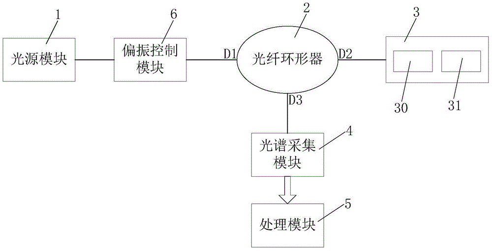
[0025] see figure 1 , is a schematic structural diagram of an all-fiber weak magnetic field measuring device according to an embodiment of the present invention. The all-fiber weak magnetic field measurement device of this embodiment includes a light source module 1 , a fiber optic circulator 2 , a magnetic sensitivity module 3 , a spectrum acquisition module 4 and a processing module 5 .

[0026] The fiber optic circulator 2 includes a first port D1 connecte...


PUM


Abstract

The invention provides an all-fiber weak magnetic field measuring device. According to the measuring device, an all-fiber FBG F-P cavity is formed in a magnetic sensitive module. When a surrounding magnetic field changes, cavity length of the all-fiber FBG F-P cavity is enabled to change by the scaling effect of magnetostrictive components and the spectral characteristics of interference signals reflected by the all-fiber FBG F-P cavity are enabled to change, and magnetic field intensity can be accurately calculated via spectral characteristic data analysis of the interference signals. With application of the mode, magnetic field intensity of a weak magnetic field can be accurately measured.

Description

technical field [0001] The invention relates to the technical field of optical fiber sensing, in particular to an all-fiber weak magnetic field measuring device. Background technique [0002] There are many fields involving magnetic field measurement, including industry, agriculture, national defense, biology, medicine, and aerospace, among which, it is more important to realize weak magnetic field measurement. There are many methods for measuring weak magnetic fields, such as fluxgate method, magneto-optical pumping, superconducting quantum device interferometry, etc., but the measuring instruments using these methods are basically composed of electronic devices, which causes the electromagnetic interference resistance of the measuring instruments And high temperature resistance is poor, so it can not work in harsh environments, which greatly limits the scope of application. Specifically, first of all, the high temperature resistance of electronic circuits is poor. When us...

Claims


Application Information

Patent Timeline
Patent Type & Authority Applications(China)
IPC IPC(8): G01R33/032
Inventor 代志勇田雕谢淼
Owner UNIV OF ELECTRONICS SCI & TECH OF CHINA
Why Eureka
Try Eureka