Mixing systems and methods

a technology of mixing systems and methods, applied in the direction of mixing, chemistry apparatus and processes, mixers, etc., can solve the problems of unmixed ingredients, waste of ingredients, and inability to obtain the desired ratio of ingredients, so as to achieve more rapid and complete mixing, less unmixed residue, and enjoyable experience

Active Publication Date: 2018-10-16
ADIP MANAGEMENT LLC
View PDF73 Cites 1 Cited by
  • Summary
  • Abstract
  • Description
  • Claims
  • Application Information

AI Technical Summary

Benefits of technology

[0004]The various systems and methods of the present invention have been developed in response to the present state of the art, and in particular, in response to the problems and needs in the art that have not yet been fully solved by currently available mixing systems and methods. The systems and methods of the present invention may provide mixing systems that provide more rapid and complete mixing, less unmixed residue, and / or an overall more enjoyable experience.
[0009]Further, in some embodiments, the first mixing surface may be shaped to define a window. The first vane may further have a plurality of bridging members that span the window. Each of the bridging members may have at least one bridging member mixing surface of the plurality of mixing surfaces. The bridging member mixing surfaces may facilitate mixture together of ingredients flowing through the window.
[0012]According to one mixing method, a mixing system with a container engagement component and a mixing component may be used. The method may include inserting the mixing component and the container engagement component into the container. The mixing component may include a shaft extending along an axis, and a plurality of mixing members arranged along the shaft. Each of the mixing members may have a plurality of mixing surfaces. The method may further include engaging an interior of the container with one or more container engagement surfaces of the container engagement component, and with the mixing component disposed within the container, moving the container repetitively to cause the mixing members to rotate about the axis. In response to rotation of the mixing members about the axis, the mixing surfaces may contact the ingredients in a manner that promotes mixture of the ingredients.
[0017]According to one alternative embodiment, a mixing system for mixing ingredients in a container may include a mixing component positionable within an interior of the container. The mixing component may include a shaft and a plurality of mixing members arranged along and coupled to the shaft. Each of the mixing members may be shaped to define a plurality of mixing surfaces. The plurality of mixing surfaces may include a first mixing surface and a second mixing surface on an opposite side of the mixing member from the first mixing surface. Each of the mixing members may be shaped to define a plurality of windows that extend between the first and second mixing surfaces to permit passage of the ingredients there through between the first and second mixing surfaces. In response to repetitive motion of the container with the mixing system disposed within the container, the mixing surfaces may contact the ingredients in a manner that promotes mixture of the ingredients together.
[0019]In some embodiments, each of the mixing members may have a substantially uniform thickness between the first mixing surface and the second mixing surface. The plurality of windows may include a primary window. Each of the mixing members may further include a plurality of bridging members that span the window. Each of the bridging members may have at least one bridging member mixing surface of the plurality of mixing surfaces. The bridging member mixing surfaces may facilitate mixture together of ingredients flowing through the window.

Problems solved by technology

Unfortunately, existing mixing systems and methods tend to leave some ingredients unmixed.
The result is that the desired ratio of ingredients is not obtained, and some ingredients are wasted.
Further, the process of cleaning a container after incomplete mixing can be somewhat more difficult.

Method used


Image

  • Mixing systems and methods
  • Mixing systems and methods
  • Mixing systems and methods

Examples


Embodiment Construction

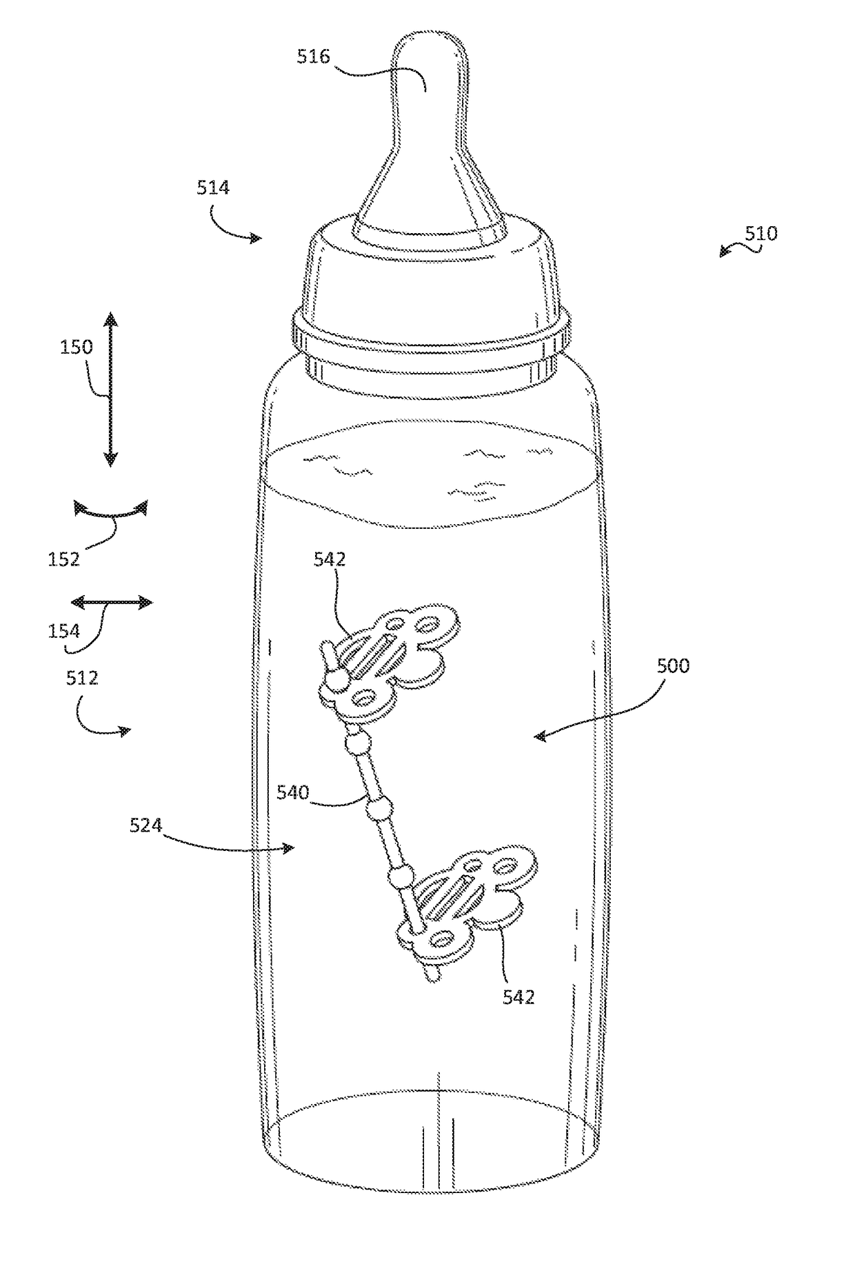
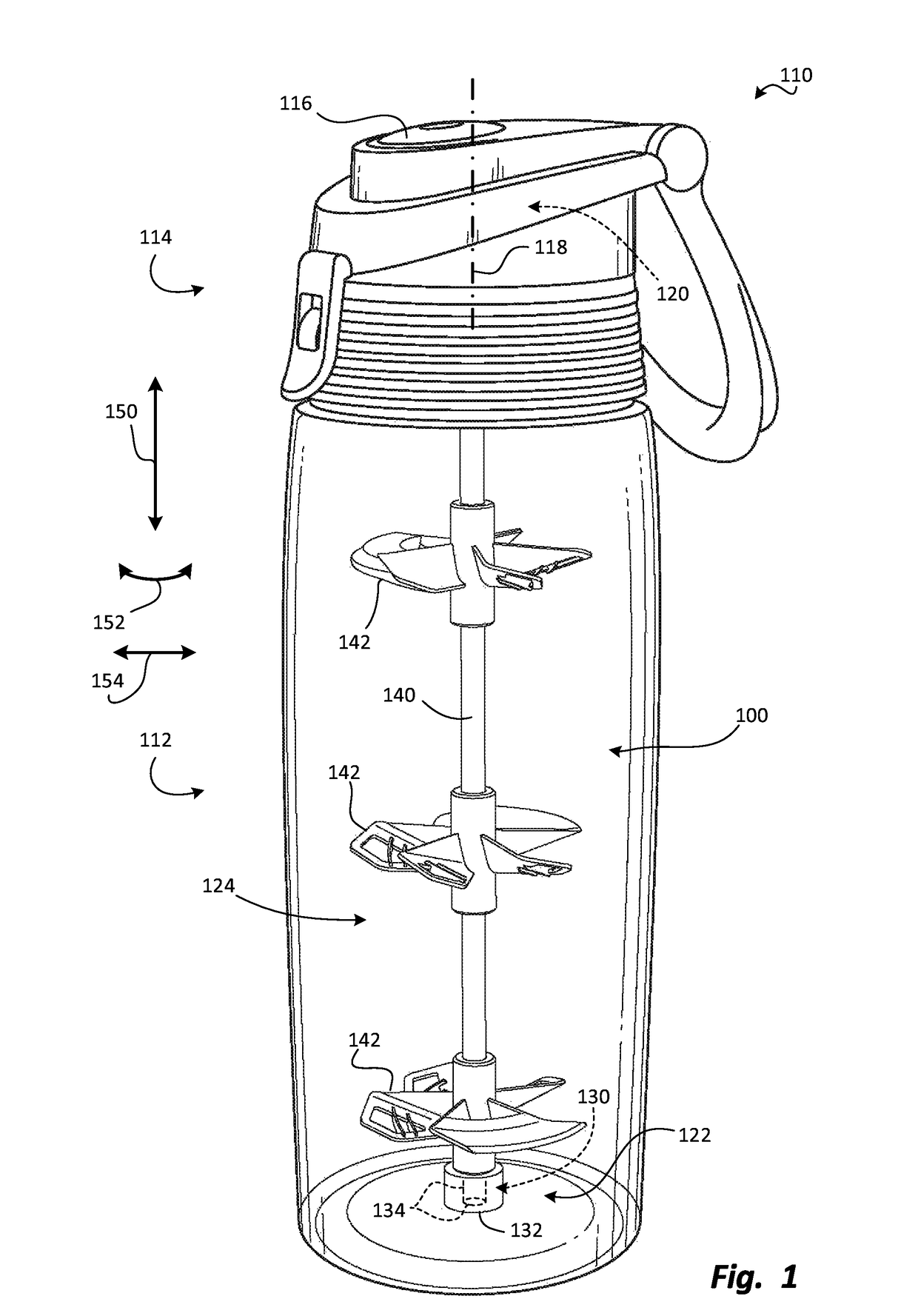
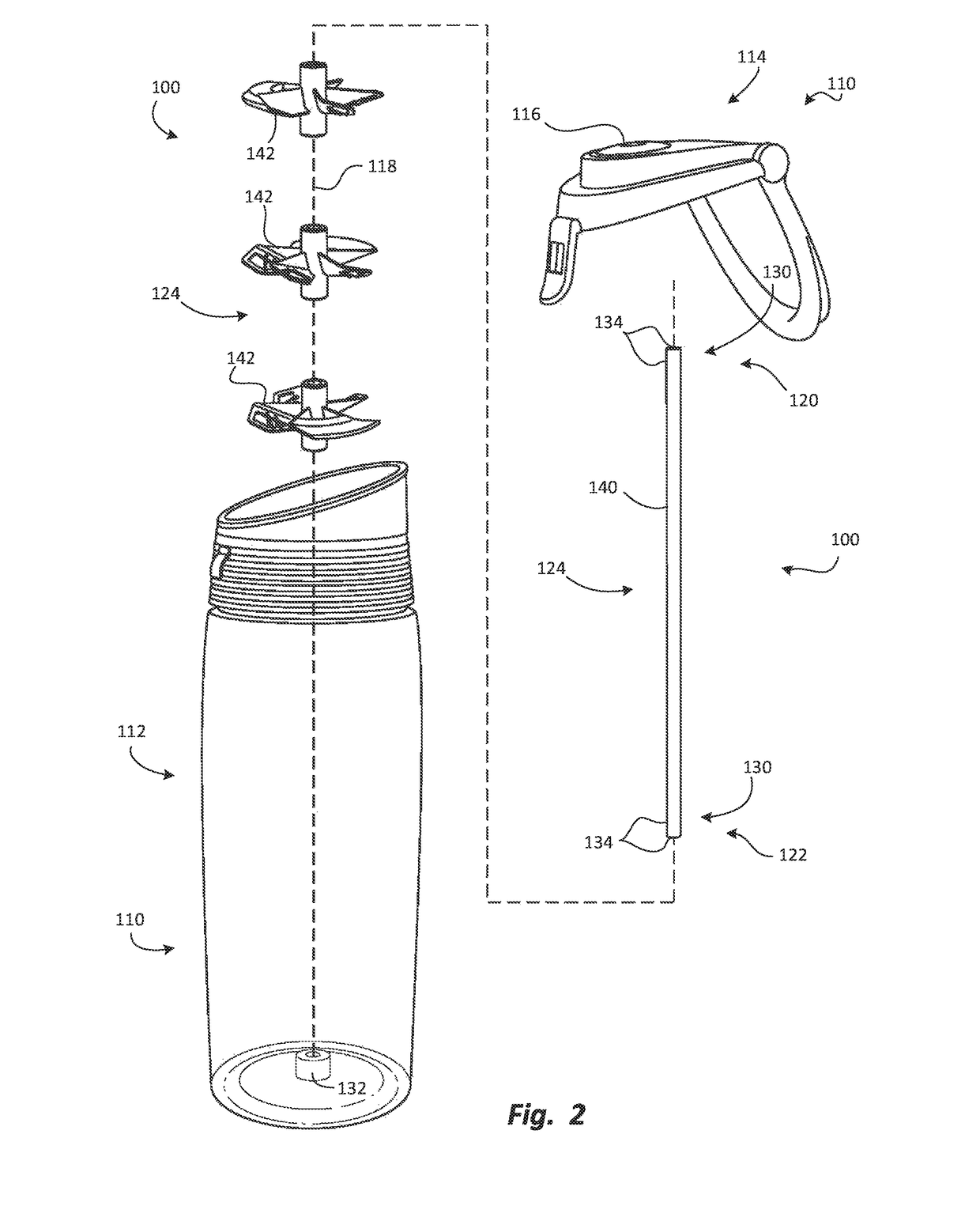
[0033]Exemplary embodiments of the invention will be best understood by reference to the drawings, wherein like parts are designated by like numerals throughout. It will be readily understood that the components of the invention, as generally described and illustrated in the Figures herein, could be arranged and designed in a wide variety of different configurations and made out of any of a wide variety of different materials, such as plastic, silicone, metal, stainless steel, aluminum and the like. Thus, the following more detailed description of the embodiments of the apparatus, system, and method, as represented in FIGS. 1 through 8, is not intended to limit the scope of the invention, as claimed, but is merely representative exemplary of exemplary embodiments of the invention.

[0034]The phrases “connected to,”“coupled to” and “in communication with” refer to any form of interaction between two or more entities, including mechanical, electrical, magnetic, electromagnetic, fluid, a...


PUM


Abstract

A mixing system and method may be used to facilitate mixture of ingredients within a container such as a bottle for baby formula, fitness drinks, medicines, food substances, art materials, and / or the like. The mixing system may include a mixing apparatus with a container engagement component that couples the mixing system to the container, and a mixing component that mixes the ingredients. The mixing component may have a plurality of mixing surfaces arranged to contact the ingredients in a manner that facilitates mixture of the ingredients together, in response to motion of the container. Alternatively, the container engagement component may be omitted. In either case, each of the mixing members may have one or more windows that facilitate mixture of the ingredients passing there through. Two or more mixing members may be connected together via a shaft and may rotate or otherwise move relative to each other on the shaft.

Description

TECHNICAL FIELD[0001]The present invention relates to systems and methods for mixing ingredients. More specifically, the present invention relates to whisk systems to be retained in various containers to facilitate mixture of ingredients of the container.BACKGROUND[0002]There are many circumstances in which disparate ingredients are to be mixed together within a container. For example, various drinks, such as hot chocolate, baby formula, protein and nutritional supplements, and the like are made by mixing a powder with a liquid such as water. Further, some medicines, such as antacids, antibiotics, and the like are rendered in drinkable form by mixing a powder, gel, solid, or other soluble material with water or other liquids.[0003]Unfortunately, existing mixing systems and methods tend to leave some ingredients unmixed. It is not uncommon, for example, to find clumps of undissolved formula in a baby bottle, even after vigorous shaking. The same can be said of many other mixing proce...

Claims


Application Information

Patent Timeline
Patent Type & Authority Patents(United States)
IPC IPC(8): B01F13/00
CPCB01F13/0022B01F13/0055B01F2215/0032B01F2215/0022B01F33/50111B01F33/25B01F33/253B01F35/32021B01F2101/14B01F2101/22
Inventor DAYTON, ANGELA PETERSON
Owner ADIP MANAGEMENT LLC
Why Eureka
Try Eureka