Engine temperature regulating device

a technology of temperature regulation device and engine, which is applied in the direction of machines/engines, mechanical equipment, transportation and packaging, etc., can solve the problems of limited amount of air in the wind hood, which accelerates the engine warm-up process, etc., and achieves the effect of facilitating the heat dissipation of the engin

Active Publication Date: 2018-10-16
KYMCO
View PDF11 Cites 4 Cited by
  • Summary
  • Abstract
  • Description
  • Claims
  • Application Information

AI Technical Summary

Benefits of technology

[0006]Since the conventional compulsory cooling device of a motorcycle has the drawbacks of causing a long warm-up process, increasing the fuel consumption, and polluting the environment, therefore, it is a primary objective of the present invention to control the timing of the cold air entering into the cooled air inlet by the adjustable fan cover module, so as to prevent a large quantity of cold air from affecting the engine warm-up time and achieve the effects of lowering the fuel consumption and reducing waste gas discharge.
[0008]Wherein, the first air intake hole of the fixed casing is set to a smooth state when the engine is not started, and after the engine is started and if the engine temperature detected by the control module is lower than a predetermined value, then the power source will be driven to connect the power source to the link rod module, so that the movable casing of the link rod module will be rotated to cover the second shelter plate of the movable casing onto the first air intake hole of the fixed casing and drive the first air intake hole into the obscured state. Now, external cold air cannot enters from the air intake hole into the engine cooled air inlet, and the amount of air in the wind hood is limited to accelerate the engine warm-up process. If the engine temperature detected by the control module reaches a predetermined value, then the power source will be turned off, so that the link rod module coupled to the movable casing will restores its initial position and let the first air intake hole of the fixed casing and the second air intake hole of the movable casing be superimposed and drive them into the smooth state. As a result, surrounding cold air is sucked into the air inlet continuously to assist the heat dissipation of the engine.

Problems solved by technology

Now, external cold air cannot enters from the air intake hole into the engine cooled air inlet, and the amount of air in the wind hood is limited to accelerate the engine warm-up process.

Method used


Image

  • Engine temperature regulating device
  • Engine temperature regulating device
  • Engine temperature regulating device

Examples


Embodiment Construction

[0015]The above and other objects, features and advantages of this disclosure will become apparent from the following detailed description taken with the accompanying drawings.

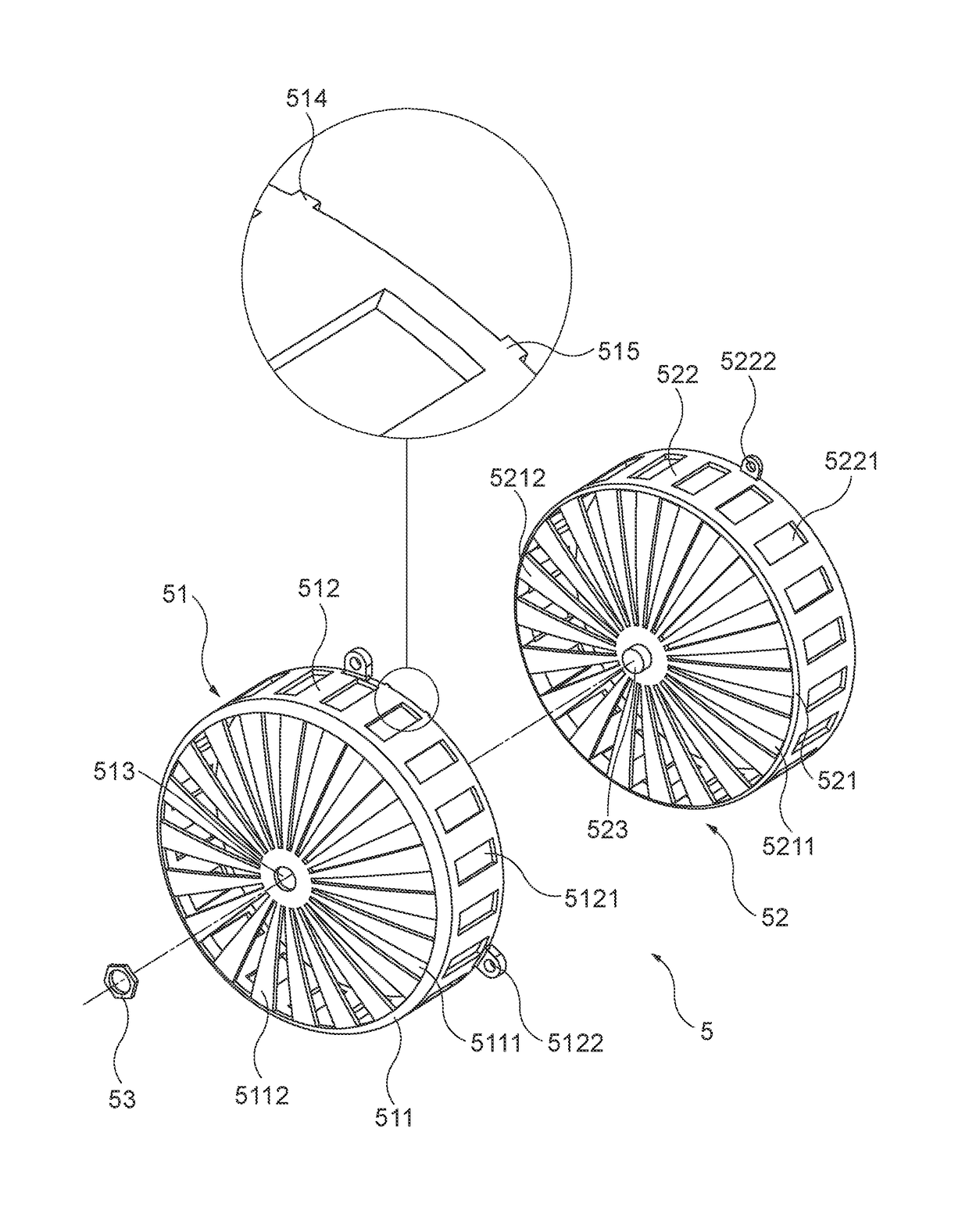
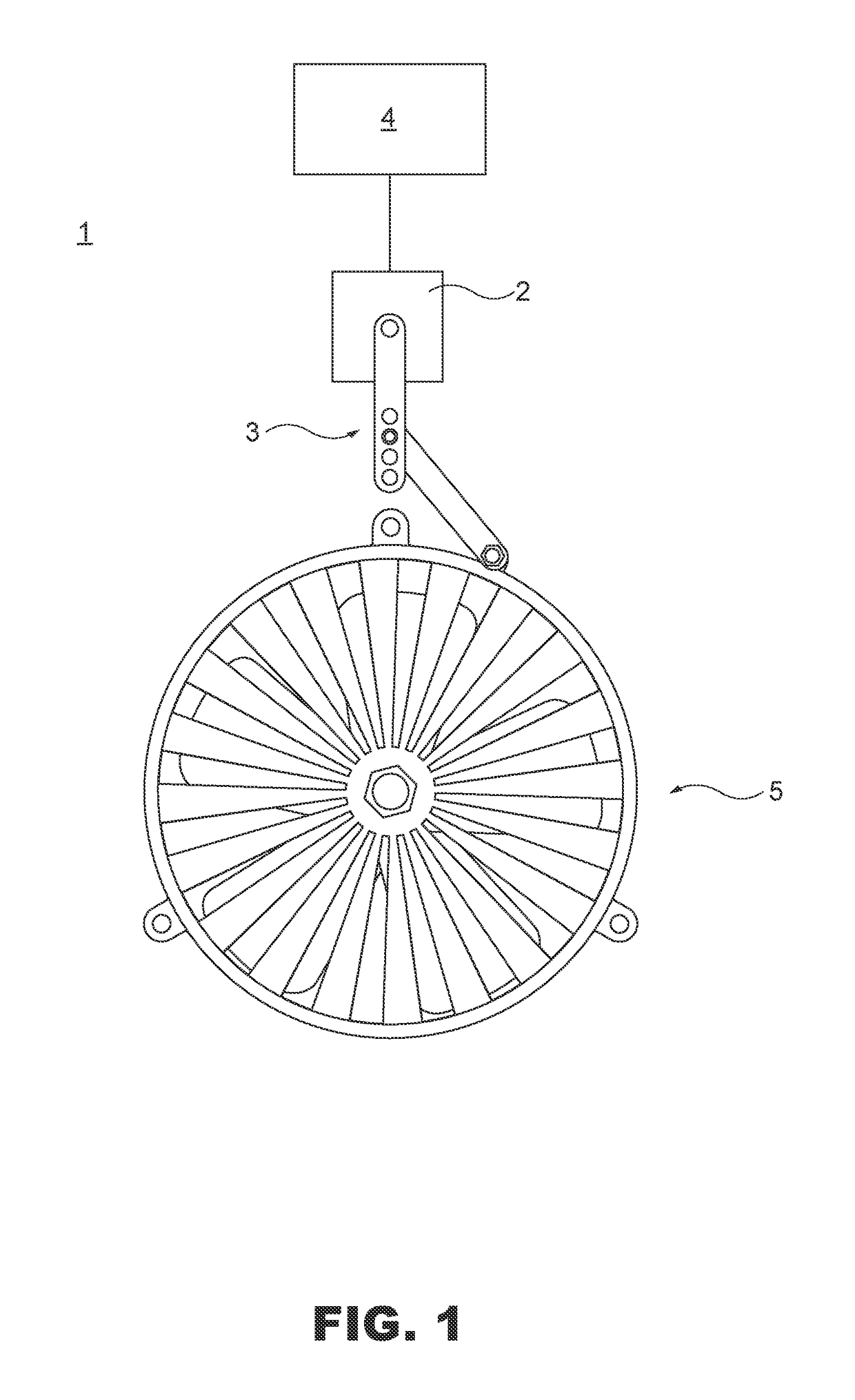
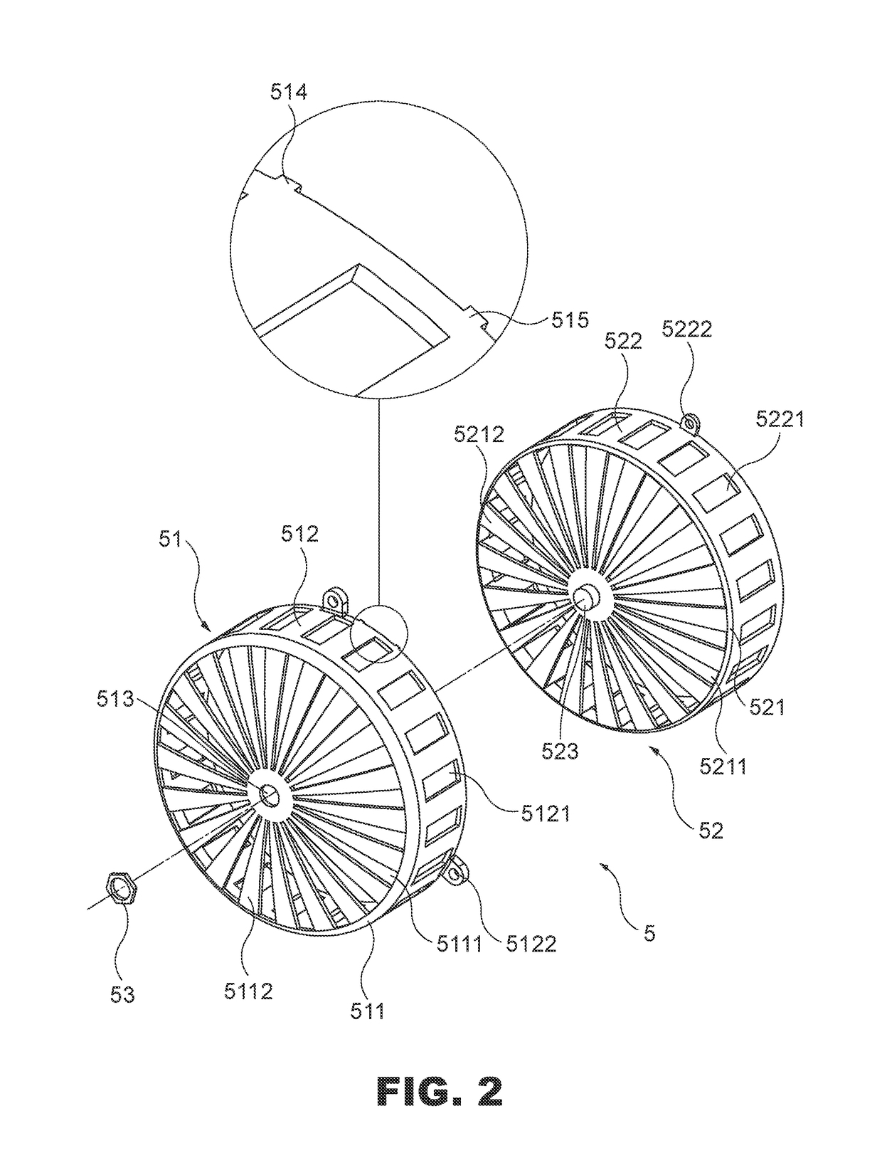
[0016]With reference to FIGS. 1 and 2 for an engine temperature regulating device of the present invention, the engine temperature regulating device 1 is installed to a casing with a cooled air inlet and comprises a power source 2, a link rod module 3, a control module 4 and a fan cover module 5. The link rod module 3 is connected to the power source 2, and the power source 2 is preferably stepper motor; the control module 4 is provided for detecting a temperature for starting the engine to obtain a temperature signal, and if the temperature signal is lower than a predetermined value, the power source 2 will be controlled and driven, or if the temperature signal reaches a predetermined value, the power source 2 will be controlled to turn off. The fan cover module 5 is covered onto the engine cooled air inlet a...


PUM


Abstract

Disclosed is an engine temperature regulating device installed to a cool air inlet of a casing of an engine. The engine temperature regulating device includes a power source, a link rod module connected to the power source, a control module and a fan cover module including a fixed casing and a movable casing. The control module is provided for detecting a temperature when the engine is turned on to control the power source to drive the link rod module, so as to control the rotation of the connected movable casing and further adjust an air intake hole of the fixed casing to a smooth or obscured state.

Description

FIELD OF INVENTION[0001]The present invention relates to a temperature regulating device, in particular to the temperature regulating device installed to a casing with a cooled air inlet of an engine, and capable of adjusting an air intake hole to a smooth or obscured state according to a temperature change at the starting stage of the engine.BACKGROUND OF INVENTIONDescription of the Related Art[0002]In general, a conventional compulsory cooling device of a motorcycle engine directly drives a cooling fan during the operation of the engine to suck surrounding cold air from the cooling fan into a wind hood, and the cold air in the wind hook cools the engine. In other words, once the engine is started, the cooling fan will be rotated accordingly. Until the engine is stopped, the cooling fan is stopped synchronously. Since a fan cover is covered and mounted onto the cooling fan for preventing foreign substances from entering into the fan cover, and the fan cover usually comes with an ai...

Claims


Application Information

Patent Timeline
Patent Type & Authority Patents(United States)
IPC IPC(8): F01P7/02F01P7/12
CPCF01P7/12F01P2050/16B60K11/06B60K11/08
Inventor LEE, CHO YUCHANG, JUI HUNGLIM, CHIN FONG
Owner KYMCO
Why Eureka
Try Eureka