Photo ionization detector with self-calibration

Active Publication Date: 2018-10-16
JIAXING BROADSENS TECH LTD
View PDF10 Cites 5 Cited by
  • Summary
  • Abstract
  • Description
  • Claims
  • Application Information

AI Technical Summary

Benefits of technology

[0004]The present invention discloses a PID system that is capable of performing self-calibrations. The system may reduce the labor cost and system down time for VOCs detections significantly. In the present invention, one or more calibration gas chambers are added to a PID s

Problems solved by technology

It is time consuming and labor intensive to calibrate a PID system, especially when the system is installed at a locatio

Method used


Image

  • Photo ionization detector with self-calibration
  • Photo ionization detector with self-calibration
  • Photo ionization detector with self-calibration

Examples


Embodiment Construction

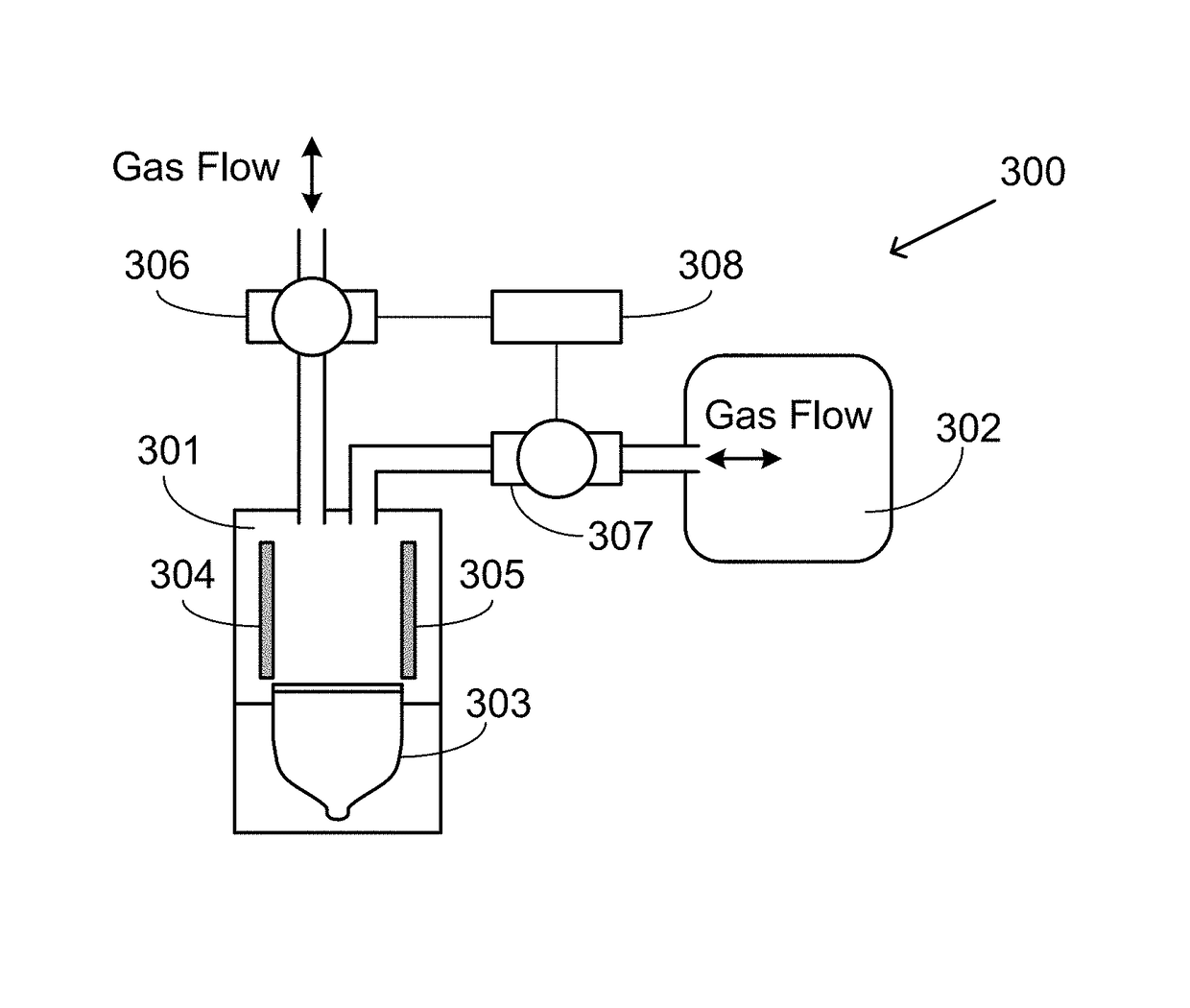
[0013]The present invention discloses a PID system that can perform calibrations automatically. The PID system comprises a measurement gas chamber and one or more calibration gas chambers. The one or more calibration gas chambers each hold a type of calibration gas. In one embodiment, VOCs measurements and calibration measurements are conducted in the same gas chamber in different times controlled by one or more gas pumping module. In another embodiment, VOCs and calibration measurements are conducted in different gas chambers, either simultaneously or one at a time.

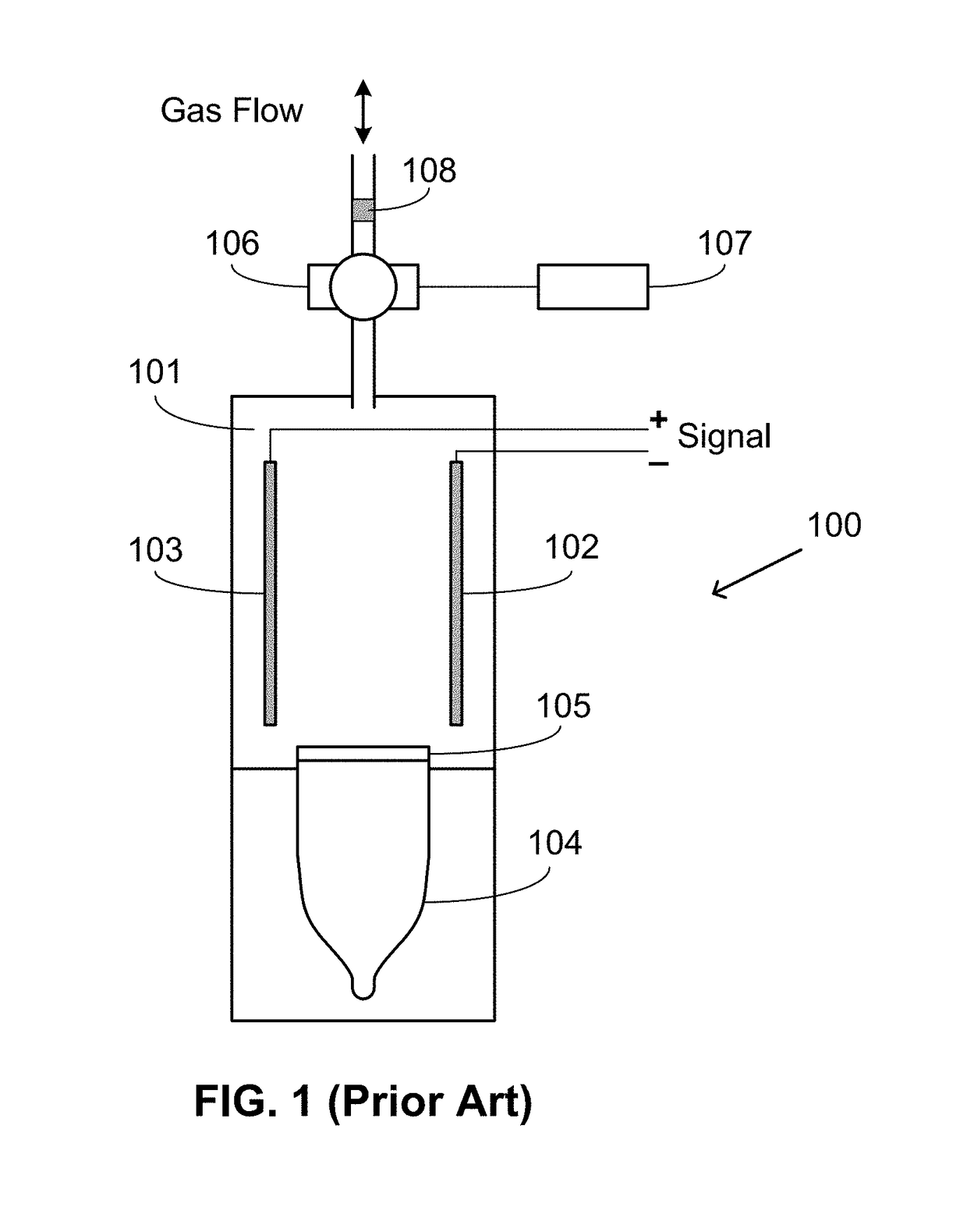
[0014]As shown in FIG. 1, a prior-art PID system 100 has a measurement gas chamber 101, electrodes 102 and 103, a UV lamp 104, a UV lamp window 105, a gas pumping module 106, a controller 107, and a dust filter 108. The gas pumping module 106 is controlled by controller 107. Dust filter 108 is used to remove dust particles from the gas to be tested. The arrow shows directions of gas flow at different times. Before a meas...


PUM


Abstract

The present invention discloses a photoionization detector (PID) system that can perform calibrations automatically. The PID system comprises a measurement gas chamber and one or more calibration gas chambers. The one or more calibration gas chambers each hold a type of calibration gas. In one embodiment, a volatile organic compounds (VOCs) measurement and a calibration measurement are conducted in the same gas chamber. In another embodiment, VOCs and calibration measurements are conducted in different gas chambers either simultaneously or at different times.

Description

CROSS-REFERENCE TO RELATED APPLICATION[0001]This application claims priority to U.S. provisional patent application Ser. No. 62 / 486,885, filed Apr. 18, 2017, the entire content of which is incorporated herein by reference.FIELD OF INVENTION[0002]This invention generally relates to the field of photoionization detection.BACKGROUND OF THE INVENTION[0003]A photoionization detector (PID) is commonly employed in the detection of volatile organic compounds (VOCs). It utilizes ultraviolet (UV) light to ionize gas molecules and measures electrical signals caused by free electrons and ions. PID systems are highly sensitive and able to detect a wide range of organic compounds and other hazardous chemicals at parts per billion (ppb) levels. PID systems have a relatively long life and do not need frequent replacement. However, since PID systems are sensitive to external factors, e.g., atmospheric pressure and ambient temperature, calibrations are conducted routinely to maintain the measurement ...

Claims


Application Information

Patent Timeline
IPC IPC(8): G01N27/66G01N33/00
CPCG01N27/66G01N33/0006G01N33/0047
Inventor ZHANG, CHANGLIU, LEI
Owner JIAXING BROADSENS TECH LTD
Why Eureka
Try Eureka