Contact device of a starter contactor

a contact device and starter technology, applied in the direction of contacts, non-polarised relays, relays, etc., can solve the problems of plate rebounding, poor contact, (s) rise, etc., and achieve the effect of reducing the occurrence of rebounding and simple assembly of the contact devi

Active Publication Date: 2018-10-16
VALEO EQUIP ELECTRIC MOTEUR
View PDF13 Cites 3 Cited by
  • Summary
  • Abstract
  • Description
  • Claims
  • Application Information

AI Technical Summary

Benefits of technology

[0010]The objective of the invention is thus to provide a solution which is inexpensive, and with simple assembly of the contact device which makes it possible to reduce the occurrence of rebounds when the coils are supplied with

Problems solved by technology

However, with the systems according to the prior art, the plate may rebound once or more on the terminals when power is supplied to the coils.
This rebound/these rebounds give(s) rise to poor contact and disrupt(s) the functioning of the starter.
In addition, the contact devices according to the prior art generally comprise a large number of parts, which gives rise to complex assembly.
In addition, the production method is very complicated using a machine, since it is necessary to be able to index the washer relative to the shoulder, and turn the latter whilst exerting pressure on the compression spring.
This embodiment is thus complex to implement.
For example, an embodiment is described in which the assembly comprises a washer with claws fitted onto the contact rod, however with an embodiment of this type, with many cycles of use, as is the case for reinforced starters (i.e. a starter which starts a thermal engine which is switched off spontaneously when the vehicle stops, for example at a red light) which require a number of cycles four times greater than with a so-called standard starter, there is a risk that the washer with claws will break or withdraw towards the fixed core, leaving a gap relative to the compression spring, and thus giving rise to

Method used


Image

  • Contact device of a starter contactor
  • Contact device of a starter contactor
  • Contact device of a starter contactor

Examples


Embodiment Construction

)

Contactor 1

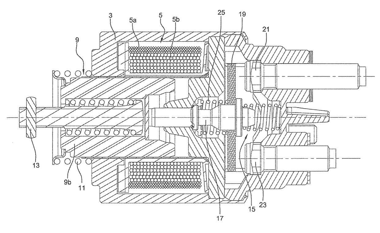
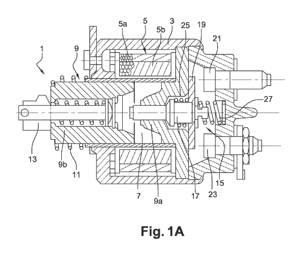
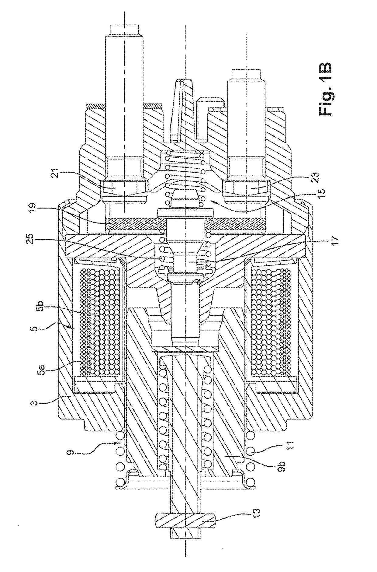
[0054]FIGS. 1A and 1B show a diagram of a starter contactor 1 comprising a cover 3 containing a set of coils 5. The set of coils 5 defines in its centre a tubular chamber 7 in which a magnetic core 9 is arranged. The magnetic core 9 comprises a fixed part 9a and a mobile part 9b which can be displaced in translation under the effect of the set of coils 5, between a position of rest represented in FIG. 1, and an active position in which the mobile part 9b comes into contact with the fixed part 9a of the magnetic core 9. A helical spring 11 assists the return to the position of rest in the absence of a supply of power to the set of coils 5. The set of coils 5 comprises a pull-in coil 5a and a contact coil 5b, the two coils 5a and 5b being supplied with power in order to displace the mobile part 9b of the magnetic core 9 from its position of rest to its active position, then the mobile part 9b is retained in the active position by the contact coil 5b alone, such as to limit...


PUM


Abstract

A contact device (15) of a starter contactor (1) comprising:—a contact rod (17) made of an electrically insulating material,—a contact strip (19) made of an electrically conducting material comprising a hole (19a) in which is mounted the contact rod (17),—a squashing spring (25),—a restoring spring (27), the contact device (15) also comprises a closure clip (33) of radial width greater than or equal to the diameter of the squashing spring (25), a radial notch (33a) being made in the closure clip (33), the radial notch (33a) receiving a portion of the contact rod (17), the squashing spring (25) being mounted compressed between the closure clip (33) and the contact strip (19) which is in abutment on a retaining collar (17a) of the contact rod (17).

Description

CROSS-REFERENCE TO RELATED APPLICATIONS AND CLAIM TO PRIORITY[0001]This application is a national stage application of International Application No. PCT / FR2015 / 051089 filed Apr. 22, 2015, which claims priority to French Patent Application No. 1454028 filed May 5, 2014, the disclosures of which are incorporated herein by reference and to which priority is claimed.FIELD OF THE INVENTION[0002]The present invention relates to the field of starters for thermal engines, in particular for motor vehicles, and more specifically the contactors of the starters which make possible the supply of power to the electric motor which drives the pinion of the starter.BACKGROUND OF THE INVENTION[0003]The contactors of the starters according to the prior art have two functions, firstly to displace the launcher which supports the pinion by means of a fork, such as to allow the pinion to engage on the crown of the thermal engine to be started, and secondly to supply power to the electric motor of the star...

Claims


Application Information

Patent Timeline
IPC IPC(8): H01H67/02H01H51/06H01H50/56H01H50/20H01H50/30H01H1/20
CPCH01H50/56H01H1/2008H01H50/30H01H51/065H01H50/20H01H2235/01
Inventor GUIGNOT, ROMAIN
Owner VALEO EQUIP ELECTRIC MOTEUR
Why Eureka
Try Eureka