
Clamping assembly having a pressure element

Active Publication Date: 2018-10-16
SIEMENS ENERGY GLOBAL GMBH & CO KG
View PDF15 Cites 0 Cited by
  • Summary
  • Abstract
  • Description
  • Claims
  • Application Information

AI Technical Summary

Benefits of technology

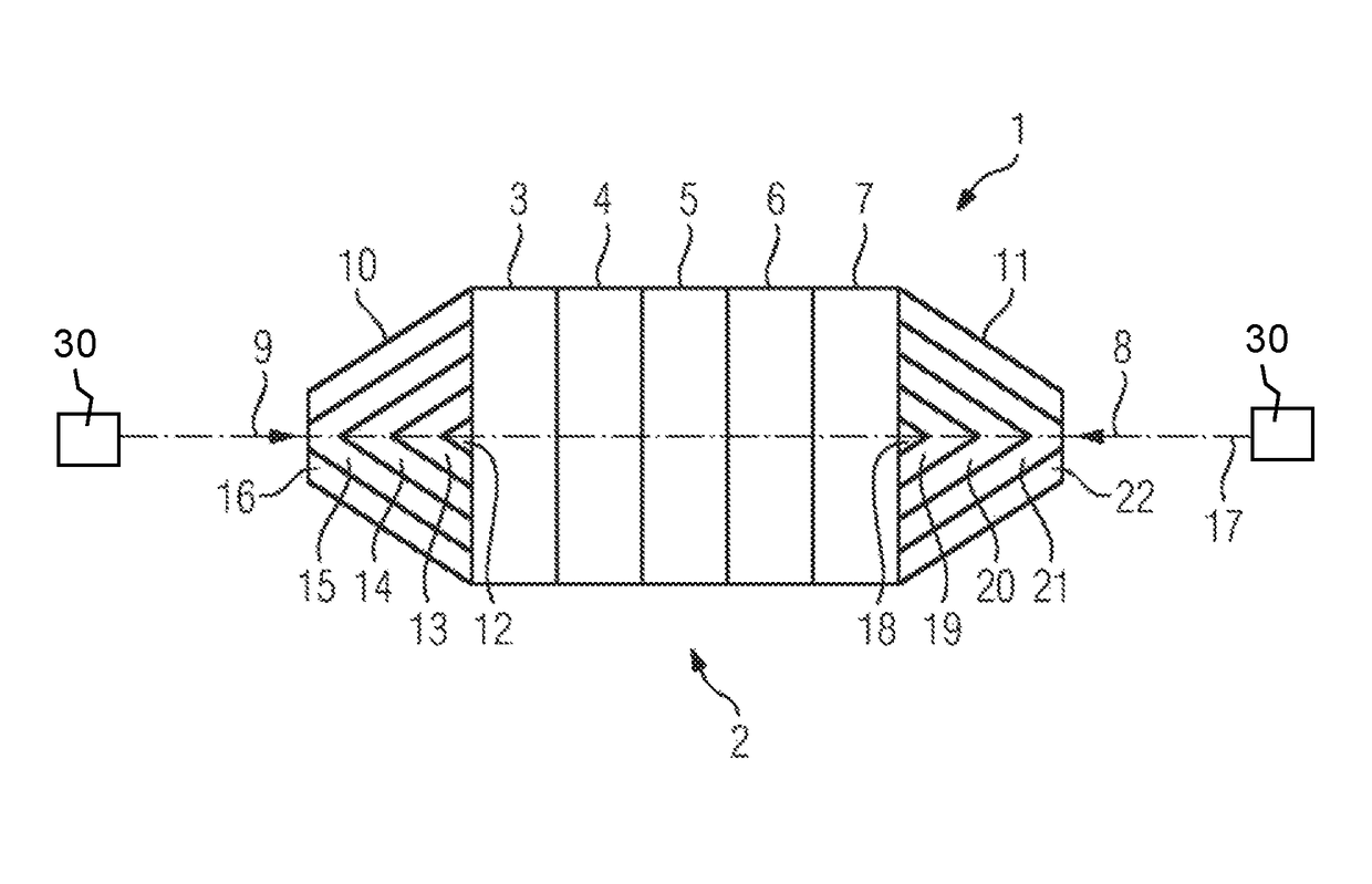
The invention relates to a pressure element that uses metal foam material to damp vibrations and control pressure distribution in a semiconductor arrangement. The use of metal foam materials with different elastic properties allows for precise control of pressure over the area. Cooling plates are assigned to each semiconductor element to remove heat and establish electrical contact, and the risk of damage to the semiconductor from non-homogeneous pressure distribution is reduced.

Problems solved by technology

This is of particular significance when the components are, for example, semiconductor chips connected in parallel which have a relatively large area in addition to being thin and brittle.
In such cases a lack of homogeneity can lead to damage to the components.

Method used


Image

  • Clamping assembly having a pressure element
  • Clamping assembly having a pressure element

Examples


Embodiment Construction

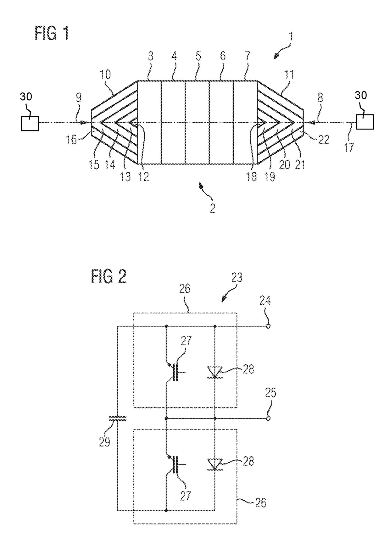
[0025]A schematic side view of a clamping assembly 1 according to the invention is shown in particular in FIG. 1. The clamping assembly 1 comprises an arrangement 2 of components 3, 4, 5, 6, 7 arranged above one another in a stack which have to be clamped together mechanically. In the exemplary embodiment of the invention illustrated in FIG. 1, the components 4 and 6 are semiconductor elements. The components 3, 5 and 7 are cooling plates that are manufactured of an electrically and thermally conductive material. Between the components 3-7 of the arrangement 2 there is thus a conductive connection, so that the components, and in particular the semiconductor modules 4, 6, constitute an electrical series circuit. The components 3-7 of the arrangement 2 are clamped together, in that a mechanical force generated by a clamping apparatus 30, is exercised on the arrangement 2 from both face sides. The clamping apparatus can, for example, be implemented in the form of a screw mechanism. The...


PUM


Abstract

A clamping assembly includes a configuration of mechanically clamped components disposed one on top of the other to form a stack. A clamping device generates a mechanical compressive force on the configuration of the components and a pressure element transmits the mechanical compressive force from the clamping device to the configuration. The pressure element contains a metal foam for a planar, homogeneous transmission of the compressive force. A sub module of a converter having at least one series circuit of power semiconductor switching units implemented as the clamping apparatus is also provided.

Description

BACKGROUND OF THE INVENTIONField of the Invention[0001]The invention concerns a clamping assembly with an arrangement of mechanically clamped components positioned above one another in a stack, a clamping device for generating mechanical compressive force on the arrangement of the components, and a pressure element for transferring the mechanical compressive force from the clamping device to the arrangement.[0002]Clamping assemblies of this type known from the prior art.[0003]Document DE 10 2011 006 990 A1 describes a column clamping assembly in which power diodes arranged above one another in a stack and heat sinks are clamped together mechanically by means of pressure elements designed as pressure plates and clamping screws. The compressive force generated by means of the clamping screws is thus transmitted to the pressure plates at specific points. In the known clamping assembly this leads to a non-homogeneous pressure distribution. The pressure generated in the region of a centr...

Claims


Application Information

Patent Timeline
IPC IPC(8): H03K17/60H01L23/40H03K17/567
CPCH01L23/4012H03K17/567H01L2023/4025H01L24/72H01L25/071H01L25/18H01L2924/13055H01L2924/00H01L25/07
Inventor BREHM, HOLGER SIEGMUNDBOEHM, MATTHIASSCHMITT, DANIEL
Owner SIEMENS ENERGY GLOBAL GMBH & CO KG
Learn More