
Native valve repair devices and procedures

a technology for repairing devices and valves, applied in the field of prosthetic devices, can solve problems such as serious cardiovascular compromise or death, heart valve damage, and reduced effectiveness

Active Publication Date: 2018-10-23
EDWARDS LIFESCIENCES CORP
View PDF180 Cites 131 Cited by
  • Summary
  • Abstract
  • Description
  • Claims
  • Application Information

AI Technical Summary

Benefits of technology

The patent describes a valve repair system that includes a delivery device and a valve repair device. The valve repair device has a paddle and a gripping member with a barbed portion that can be attached to the patient's valve tissue. The system includes a gripper control mechanism that moves the gripping member between an open and closed position. The mechanism includes a suture and a pushing member that work together to flex the gripping member and move the barbed portion. The invention allows for easy repair of valves without the need for an open heart surgery. The technical effects of this patent are improved efficiency and accuracy in valve repair, reducing the risk of complications and saving lives.

Problems solved by technology

These heart valves can be damaged, and thus rendered less effective, by congenital malformations, inflammatory processes, infectious conditions, or disease.
Such damage to the valves can result in serious cardiovascular compromise or death.
However, open heart surgeries are highly invasive and are prone to many complications.
Therefore, elderly and frail patients with defective heart valves often went untreated.
This results in a longer operation time and the patient's leaflets are joined at the sides, restricting blood flow.
Both the surgical and clip treatments are thought to create stress on patient leaflets.

Method used


Image

  • Native valve repair devices and procedures
  • Native valve repair devices and procedures
  • Native valve repair devices and procedures

Examples


Embodiment Construction

[0081]The following description refers to the accompanying drawings, which illustrate specific embodiments of the invention. Other embodiments having different structures and operation do not depart from the scope of the present invention.

[0082]Exemplary embodiments of the present disclosure are directed to devices and methods for repairing a defective heart valve. It should be noted that various embodiments of native valve reparation devices and systems for delivery are disclosed herein, and any combination of these options can be made unless specifically excluded. In other words, individual components of the disclosed devices and systems can be combined unless mutually exclusive or otherwise physically impossible.

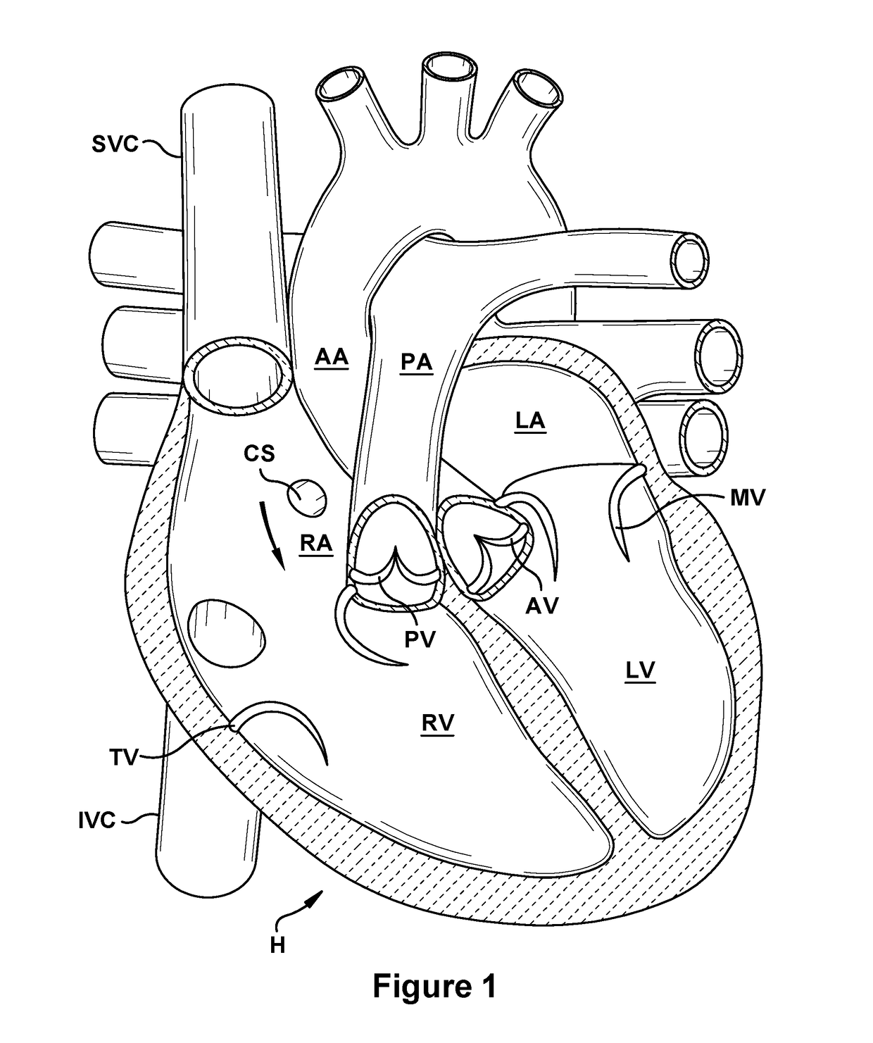
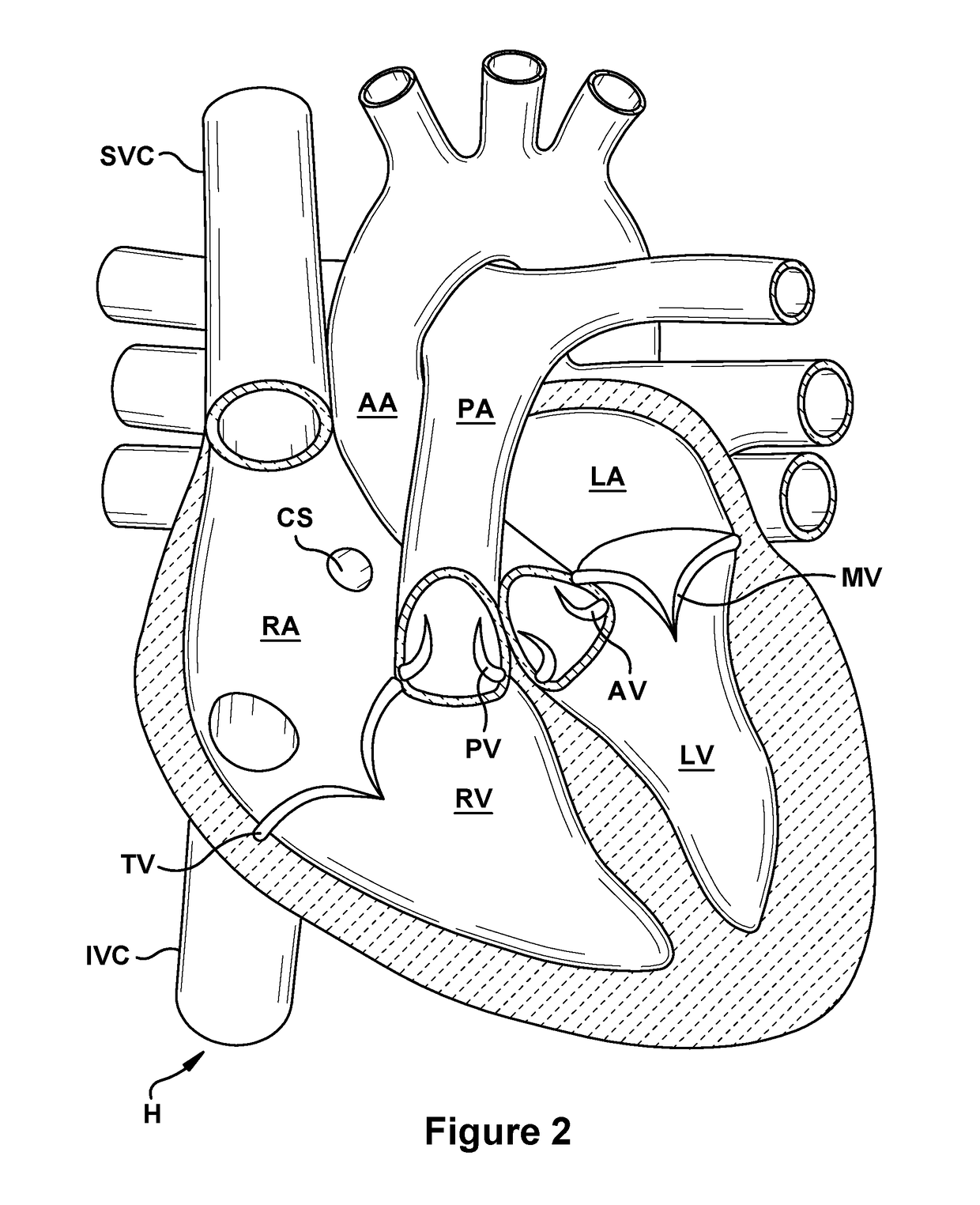
[0083]FIGS. 1 and 2 are cutaway views of the human heart H in diastolic and systolic phases, respectively. The right ventricle RV and left ventricle LV are separated from the right atrium RA and left atrium LA, respectively, by the tricuspid valve TV and mitral valve MV; ...


PUM


Abstract

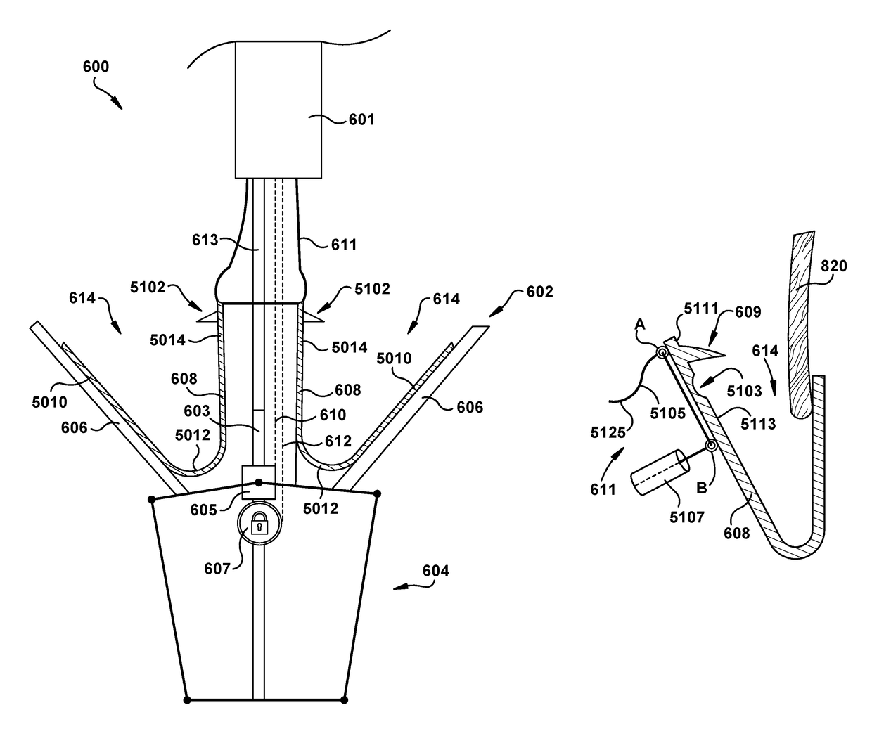
A system for implanting a repair device onto a native valve of a natural heart to repairing the native valve of a patient during a non-open-heart procedure. The system includes a paddle and a gripping member. The paddle is movable between an open position and a closed position. The gripping member has a weakened portion and a barbed portion. The barbed portion is configured to secure the gripping member to valve tissue of the native valve of the patient. A gripper control mechanism is configured to move the gripping member between an open position and a closed position. The gripper control mechanism comprises a suture removably attached to the gripping member at a first connection point and a pushing member configured to engage the gripping member at a second connection point. The weakened portion is between the first and second connection points. The pushing member is configured to push on the gripping member and the suture is configured to pull on the gripping member to flex the weakened portion and pivot the barbed portion.

Description

FIELD OF THE INVENTION[0001]The present application relates generally to prosthetic devices and related methods for helping to seal native heart valves and prevent or reduce regurgitation therethrough, as well as devices and related methods for implanting such prosthetic devices.BACKGROUND OF THE INVENTION[0002]The native heart valves (i.e., the aortic, pulmonary, tricuspid, and mitral valves) serve critical functions in assuring the forward flow of an adequate supply of blood through the cardiovascular system. These heart valves can be damaged, and thus rendered less effective, by congenital malformations, inflammatory processes, infectious conditions, or disease. Such damage to the valves can result in serious cardiovascular compromise or death. For many years the definitive treatment for such damaged valves was surgical repair or replacement of the valve during open heart surgery. However, open heart surgeries are highly invasive and are prone to many complications. Therefore, el...

Claims


Application Information

Patent Timeline
IPC IPC(8): A61F2/24A61B17/10A61B17/00
CPCA61F2/2427A61F2/2466A61B2017/00243A61F2220/0075A61F2220/0016A61B17/0643A61B17/122A61B17/1285A61B2017/00367A61F2/246
Inventor METCHIK, ASHER L.TYLER, II, GREGORY SCOTTWINSTON, MATTHEW T.DELGADO, SERGIOFRESCHAUF, LAUREN R.DIXON, ERIC R.SIEGEL, ALEXANDER J.
Owner EDWARDS LIFESCIENCES CORP
Learn More