Aircraft and fuselage cooling structure
a cooling structure and fuselage technology, applied in the direction of fuselages, air-treatment apparatus arrangements, energy-saving board measures, etc., can solve the problems of fuel efficiency deterioration, local temperature rise in the lower part of the fuselage, and increased size of the fairing, so as to suppress the local temperature rise of the fuselage
- Summary
- Abstract
- Description
- Claims
- Application Information
AI Technical Summary
Benefits of technology
Problems solved by technology
Method used
Image
Examples
second embodiment
[0093]Next, a second embodiment of the present invention will be described with reference to FIG. 4.
[0094]In the second and subsequent embodiments, differences from the first embodiment will be mainly described. The same components as with the first embodiment are given the same reference signs.
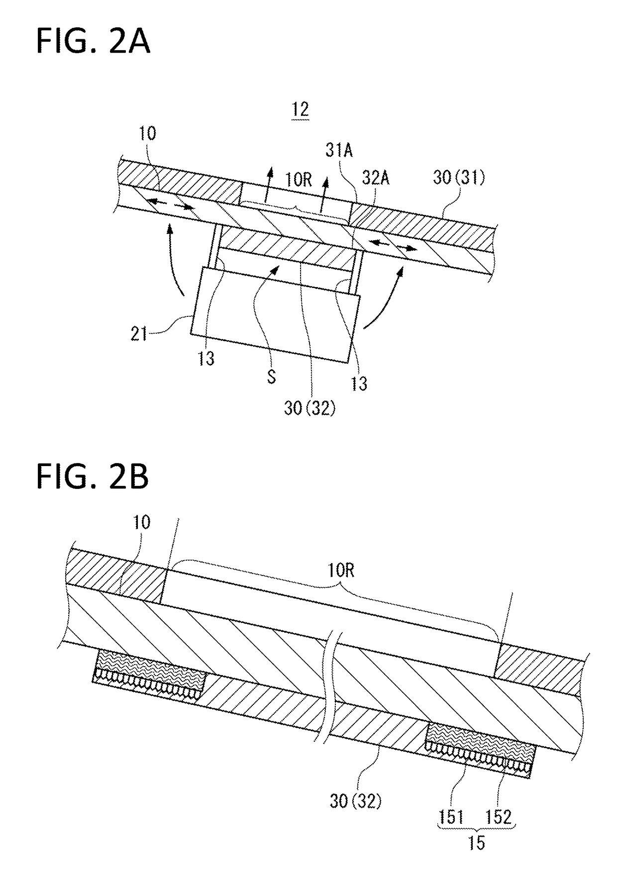
[0095]As shown in FIG. 4A, in the second embodiment, the end edges 31A of the inner heat insulation material 31 which are adjacent to the region 10R are smoothly formed so that air flows smoothly around the region 10R of the fuselage 10 exposed to the inside of the fuselage 10. The end edges 31A of the inner heat insulation material 31 may be cut smoothly, or may be formed smoothly by pressing with a die of a desired shape. The end edges 31A of the inner heat insulation material 31 can be formed smoothly by any other appropriate method.
[0096]The end edges 31A of the inner heat insulation material 31 adjacent to the region 10R are rising gently in the thickness direction of the inner heat insu...
third embodiment
[0100]Next, a third embodiment of the present invention will be described with reference to FIG. 5.
[0101]In the third embodiment, an air current Ac as a cooling source is supplied from the inside of the fuselage 10 toward the region 10R exposed to the inside of the fuselage 10.
[0102]For example, air conditioning exhaust, which circulates inside the pressurized compartment 12 as air conditioning air produced by the air conditioning system 20 and is thereafter discharged to the outside of the aircraft through the inside of the fairing 11, can be used as the air current Ac. For this purpose, a duct 16 can be routed from a compartment or a pipeline, where the air conditioning exhaust flows, toward the region 10R.
[0103]Otherwise, low-temperature air taken out from the air cycle of the air conditioning pack 21 can also be supplied as the air current Ac to the region 10R.
[0104]Even if the temperature of the air current Ac is similar to the temperature of air inside the fuselage 10 present ...
fourth embodiment
[0111]Next, a fourth embodiment of the present invention will be described with reference to FIG. 6.
[0112]In the fourth embodiment, the air current Ac is supplied through a duct 18 to the space between the lower part 10A of the fuselage 10 and the fairing 11.
[0113]The outlet of the duct 18 is preferably disposed near the corresponding region 10R. In this embodiment, air is blown from the duct 18 into the space between the outer heat insulation material 32 and the air conditioning pack 21.
[0114]As in the third embodiment, air conditioning exhaust, or low-temperature air taken out from the air cycle of the air conditioning pack 21, can be used as the air current Ac.
[0115]The flow of air inside the fairing 11 is promoted by the air current Ac flowing out of the duct 18. As a result, heat release to the surface of the fairing 11 is promoted, so that the air conditioning pack 21 and the region 10R of the fuselage 10 can be cooled accordingly.
[0116]As with the third embodiment, this embod...
PUM
 Abstract
Description
Claims
Application Information
 - R&D
- Intellectual Property
- Life Sciences
- Materials
- Tech Scout
- Unparalleled Data Quality
- Higher Quality Content
- 60% Fewer Hallucinations
Browse by: Latest US Patents, China's latest patents, Technical Efficacy Thesaurus, Application Domain, Technology Topic, Popular Technical Reports.
© 2025 PatSnap. All rights reserved.Legal|Privacy policy|Modern Slavery Act Transparency Statement|Sitemap|About US| Contact US: help@patsnap.com


