Overhead luggage compartment for airplanes, and airplane

Active Publication Date: 2018-10-23
FACC
41 Cites 7 Cited by

AI-Extracted Technical Summary

Problems solved by technology

However, the known luggage compartments have the disadvantage of that the spring force of the holding device must be overcome independently of the load stat...

Benefits of technology

[0035]According to an alternative variant of the embodiment it is provided that the force transmission element is connected to a stop, by means of which the force transmission element can be lifted together with the joint ...

Abstract

An overhead luggage compartment for airplanes, comprising a stationary luggage compartment element which can be secured to a structural element and comprising a movable luggage compartment element which can be loaded with a piece of luggage, said compartments being connected together by a joint such that the movable luggage compartment element can be pivoted between an open position and a closed position. The overhead luggage compartment may comprise a device for holding the movable luggage compartment element in the open position, said device having a force transmission element which is connected to the joint between the stationary luggage compartment element and the movable luggage compartment element.

Application Domain

Stowage devices

Technology Topic

Image

  • Overhead luggage compartment for airplanes, and airplane
  • Overhead luggage compartment for airplanes, and airplane
  • Overhead luggage compartment for airplanes, and airplane

Examples

  • Experimental program(1)

Example

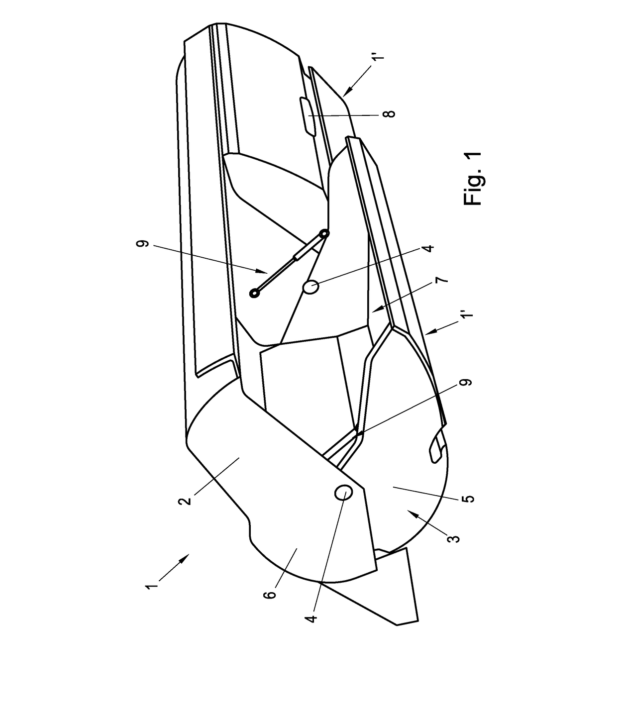
[0050]FIG. 1 shows an overhead luggage compartment 1 for airplanes, comprising in the shown embodiment two identically designed luggage compartment modules 1′. Of course, only one such luggage compartment module 1′ or more than two such luggage compartment modules 1′ may be provided. The luggage compartment modules 1′ each comprise a stationary luggage compartment element 2, which can be connected to a structural element, in particular to an aircraft fuselage (not shown). Moreover, the luggage compartment 1 comprises a movable luggage compartment element 3 which may be designed as a trough, semi-chute or U-shaped luggage compartment to accommodate pieces of luggage. The movable luggage compartment element 3 is suspended on the stationary luggage compartment element 2 on both sides by means of joints 4 having joint axes 4′. The joints 4 are located on overlapping sections of sidewalls 5 of the movable luggage compartment element 3 and sidewalls 6 of the stationary luggage compartment element 2. The movable luggage compartment element 2 can be pivoted between an open position (cf. the left luggage compartment module 1′ in FIG. 1), in which a load opening 7 is released, and a closed position (cf. the right luggage compartment module 1′ in FIG. 1), in which the load opening 7 is closed. For this purpose, the movable luggage compartment element 3 comprises a grip element 8 on the visible side, with which the luggage compartment 1 can be opened or closed. Furthermore, FIG. 1 shows lifting springs 9 between the movable luggage compartment element 3 and the stationary luggage compartment element 2, with which the pivot of the movable luggage compartment element 3 from the open position into the closed position is supported. The spring element is preferably connected to a damping element (not shown).
[0051]As can be seen from FIGS. 2, 3 the luggage compartment 1 additionally comprises a device 10 for holding the movable luggage compartment element 3 in the open position, which is designed to detect a load state of the movable luggage compartment element 3. In the shown embodiment, the device 10 comprises a force transmission element 11, which is connected to the joint 4 between the stationary luggage compartment element 2 and the movable luggage compartment element 3. Of course, both opposite joints 4 of the luggage compartment 1 may be designed identically. When the movable luggage compartment element is in the open position (cf. FIG. 2), the joint 4 can be moved depending on the load state of the movable luggage compartment element 3 in a vertical direction. FIG. 3 schematically shows a piece of luggage having a weight 12 generating a force in the direction of arrow 13. Due to the weight-dependent movement of the joint 4 the force transmission element 11 is arranged in an active position in the unloaded state (cf. FIG. 2) and in an inactive position in the loaded state (cf. FIG. 3). In the active position of the force transmission element 11, a holding torque is exerted which counteracts the pivot of the movable luggage compartment element 3 from the open position in the direction of the closed position such that the movable luggage compartment element 3 is held in the open position. For this purpose, the stationary luggage compartment element 2 comprises a contact element 14, which in the active position engages the force transmission element 11, whereas in the inactive position of the force transmission element 11 the engagement between the force transmission element 11 and the contact element 14 is released.
[0052]According to FIGS. 2, 3 the force transmission element 11 comprises a frictional surface 15, with which a frictional force depending on the load state of the movable luggage compartment element 3 can be transferred onto a corresponding frictional surface 15′ of the contact element. In the shown embodiment, the frictional surface 15 is provided on the circumference of the force transmission element 11, which is connected to the joint 4 in a torque-proof manner. Accordingly, the force transmission element 11 is pivoted together with the movable luggage compartment element 3 upon closing of the luggage compartment 1. In the unloaded state of the luggage compartment 1 (cf. FIG. 2), a frictional torque is generated by the friction between the frictional surfaces 15, 15′, which is overcome by the user upon closing of the luggage compartment 1. To adjust a suitable holding or frictional torque, the frictional surface 15 on the force transmission element 11 and/or the frictional surface 15′ on the contact element 14 may comprise an anti-slip material.
[0053]As may be further seen from FIGS. 2, 3, at least one spring element 16 for biasing the force transmission element 11 in the direction of the active position is provided. By loading the movable luggage compartment element 3 with the piece of luggage, cf. weight 12 in FIG. 3, the force transmission element 11 can be moved against the force of the spring element 16 essentially in a vertical direction downwards and into the inactive position. Thus, the frictional surfaces 15, 15′ are arranged at a distance such that the frictional or holding torque of the holding device 10 disappears in the open position of the movable luggage compartment element 3.
[0054]FIGS. 4A-F show alternative embodiments of the force transmission element 11, the suspension of the joint 4 on the luggage compartment 1 being shown only schematically for better overview. In FIG. 4A to FIG. 4C the opening operation of the luggage compartment is shown in the unloaded state, FIG. 4A showing the closed position, FIG. 4B showing an intermediate position and FIG. 4C showing an open position. FIGS. 4D to 4F illustrate the closing operation of the loaded luggage compartment, FIG. 4D showing the open position, FIG. 4E showing the intermediate position and FIG. 4F showing the closed position.
[0055]As can be seen from FIG. 4A, in this embodiment the force transmission element 11 is also connected to the joint 4 between the movable luggage compartment element 3 and the stationary luggage compartment element 2 in a torque-proof manner such that the force transmission element 11 can be pivoted by pivoting the movable luggage compartment element 3.
[0056]According to FIG. 4E and FIG. 4F the force transmission element 11 comprises a locking element 18 in the form of a locking recess 22, which interacts with a corresponding, bar-shaped locking element 19 of the contact element 14. Depending on the load state, in the open position of the movable luggage compartment element 3, the locking elements 18, 19 are arranged in a locked position (cf. FIG. 4C) or in a release position (cf. FIG. 4D). The locking element 19 of the contact element 14 is connected to a holding spring 20 such that the locking element 19 of the contact element 14 can be moved against the force of the holding spring 20 from the locked position (cf. FIG. 4C) in the direction of the release position (cf. FIG. 4B) in the unloaded state of the luggage compartment 1.
[0057]In addition, FIG. 4C and FIG. 4D schematically shows a stop 26, with which the movement of the locking element 19 is limited. In addition, a stop 27 is schematically shown, by which it is ensured that in the loaded state, upon reaching the closed position of the luggage compartment 1, the joint axis 4′ is lifted to a position in which the luggage compartment 1 is closed in a gap-free manner.
[0058]According to FIGS. 5 to 7 the locking element 19 of the contact element 14 is formed by a ball element 21 loaded by the spring element 20, with which ball element 21 a locking recess 22 of the force transmission element 11 interacts. Of course, the locking recess 22 may be provided alternatively on the locking element 19 and the ball element 21 on the force transmission element 11. In the open position of the movable luggage compartment element 3, the ball element 21 is partially arranged within the locking recess 22 of the locking element 18 of the force transmission element 11, if in the unloaded state of the luggage compartment 1 the force transmission element 11 is in the upper, active position. In the loaded state, the ball element 21 is arranged outside the locking recess 22 of the locking element 18 of the force transmission element 11. Upon closing the luggage compartment 1, the force transmission element 11 is pivoted in the direction of arrow 17 (cf. FIG. 6), the locking elements 18, 19 being released from their locking engagement.
[0059]As can be further seen from FIGS. 5 to 7, for biasing the force transmission element 11 in the direction of the active position, the spring element 16 comprises two further spring-loaded ball elements 23 in this embodiment, which roll on the corresponding support surface of the force transmission element 11. In the shown embodiment, the force transmission element 11 with the locking element 18 is designed as a cam element having a non-round, e.g. oval support surface. This causes the joint axis 4′ to be lifted to the initial position prior to loading during the closing operation in the loaded state. Thus, the luggage compartment is arranged in the closed position in a gap-free manner.
[0060]According to FIG. 8 the locking element 18 of the force transmission element 11 is designed as a locking disk connected to the joint 4 in a torque-proof manner which locking disk comprises a locking projection 24 for locking with the locking element 19 of the contact element 14. In the shown embodiment, the locking element 19 of the contact element 14 is formed by a spring bar 25 with a bar element 25′ and a spring element 25″. The spring bar 25 can be moved by the locking element 18 of the force transmission element 11 between the locked position (cf. FIG. 7) and the release position (not shown) in that the movable luggage compartment element 3 is pivoted from the open position in the direction of the closed position.

PUM

no PUM

Description & Claims & Application Information

We can also present the details of the Description, Claims and Application information to help users get a comprehensive understanding of the technical details of the patent, such as background art, summary of invention, brief description of drawings, description of embodiments, and other original content. On the other hand, users can also determine the specific scope of protection of the technology through the list of claims; as well as understand the changes in the life cycle of the technology with the presentation of the patent timeline. Login to view more.

Similar technology patents

Method for Quantitatively Analyzing Residual Cl in Zinc Ferrite

ActiveUS20200333303A1Prevent from formComplete combustionChemical analysis using combustionSamplingZinc ferriteIron chloride
Owner:LG CHEM LTD

Ink fountain liner and blade guard

InactiveUS20120240799A1Prolonged lifePrevent from formOffice printingPrinting press partsEngineeringAdhesive
Owner:SANDEN NORTH AMERICA

Classification and recommendation of technical efficacy words

  • Prevent from form

Biocompatible Mesh Implant

ActiveUS20130253645A1Increase tolerancePrevent from formMammary implantsBreast implantGeneral surgery
Owner:PFM MEDICAL

Spiral electrodeionization device with uniform operating characteristics

InactiveUS20060163056A1Prevent from formEnhance removalCellsIon-exchange column/bed processesIon exchangeIon
Owner:IONICS INC

Woman's undergarment to remedy chest wrinkles

ActiveUS8047892B1Prevent from formComfortably wearBrassieresWrinkleTorso
Owner:DEMPSEY DARLENE S
Why Eureka
Try Eureka