
Power tube connection structure of power amplifier and power amplifier

Active Publication Date: 2018-12-25
HUAWEI TECH CO LTD
View PDF31 Cites 0 Cited by
  • Summary
  • Abstract
  • Description
  • Claims
  • Application Information

AI Technical Summary

Benefits of technology

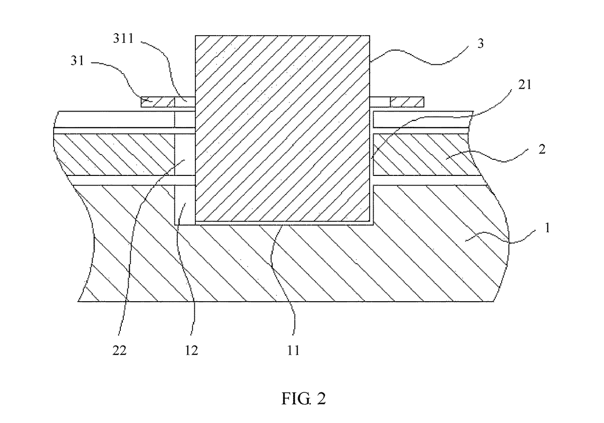
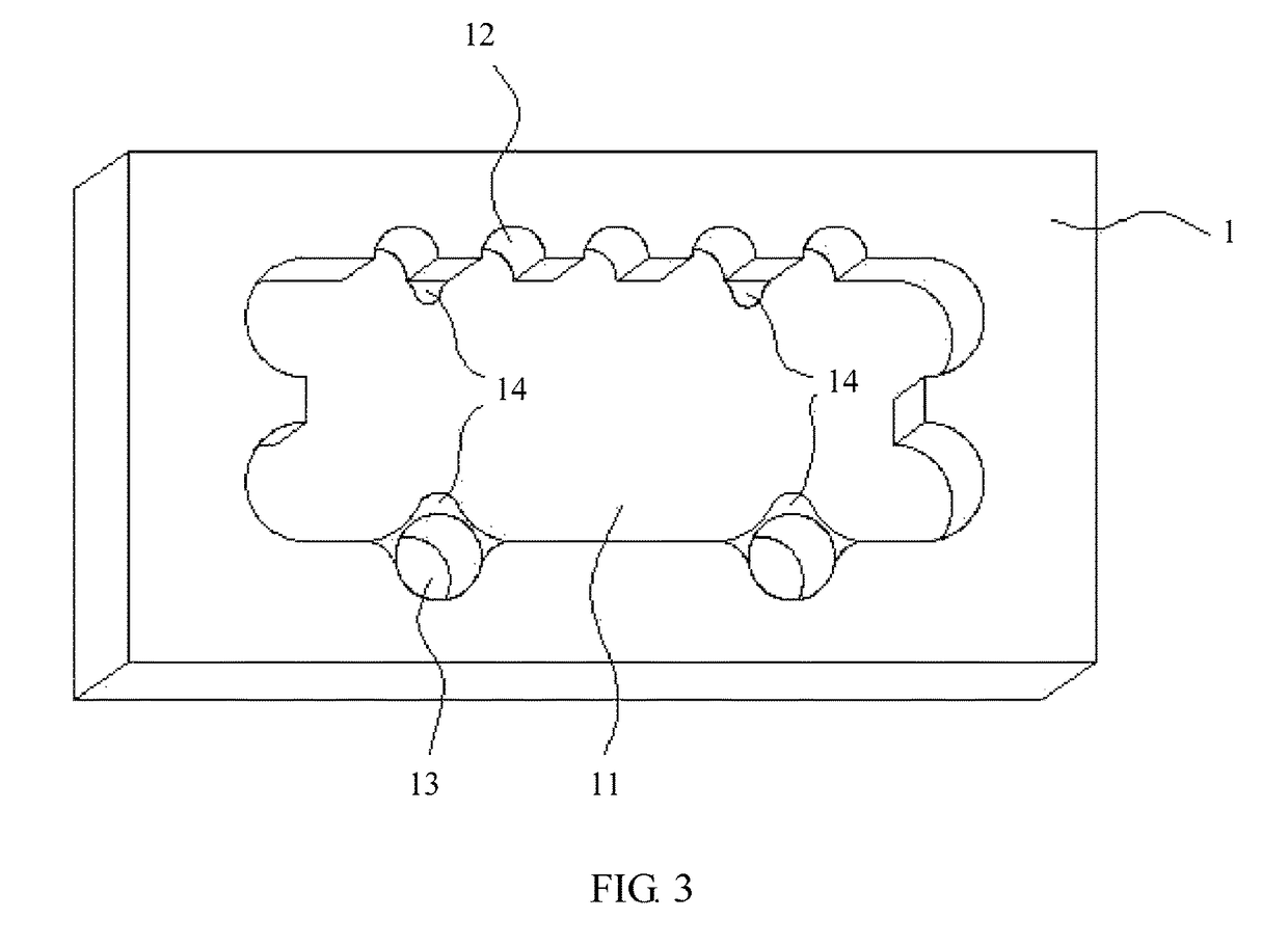
The present invention provides a structure for connecting power amplifiers using a power tube. This structure prevents a solder void from forming at the bottom of the power tube. This is achieved by creating a solder flux escape channel in the mounting groove of the power amplifier, allowing gas solder flux to flow out of the amplifier during welding. This prevents the solder void from forming during the connection process.

Problems solved by technology

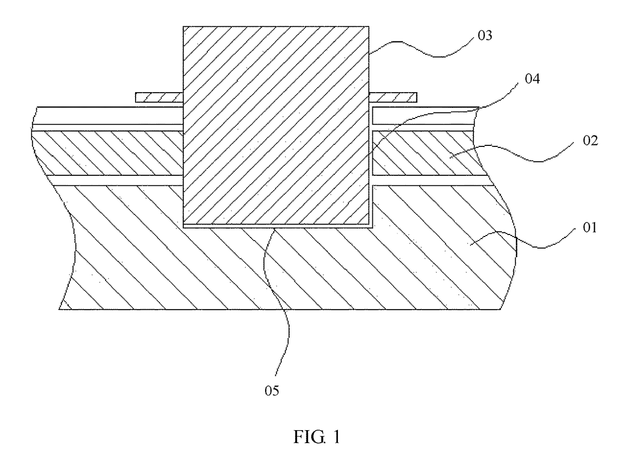
However, there is consequently no escape channel for gas solder flux during reflow soldering, and a solder void is formed at the bottom of the power tube 03.

Method used


Image

  • Power tube connection structure of power amplifier and power amplifier
  • Power tube connection structure of power amplifier and power amplifier
  • Power tube connection structure of power amplifier and power amplifier

Examples


Embodiment Construction

[0021]The following clearly describes technical solutions in embodiments of the present invention with reference to the accompanying drawings. The described embodiments are merely some but not all of the embodiments of the present invention. All other embodiments obtained by a person of ordinary skill in the art based on the described embodiments of the present invention without creative efforts shall fall within the protection scope of the present invention.

[0022]In the descriptions of the present invention, it should be understood that, position or location relationships indicated by the terms “center”, “upper”, “lower”, “ahead”, “behind”, “left”, “right”, “perpendicular”, “horizontal”, “top”, “bottom”, “inner”, “outer”, and the like are exemplary position or location relationships based on the accompanying drawings, and are merely intended for ease of describing the present invention and simplification of description, instead of indicating or implying that the apparatuses or comp...


PUM


Abstract

A power tube connection structure includes a substrate, a printed circuit board, and a power tube, where a through groove allowing the power tube to pass through is cut into the printed circuit board, a mounting groove is cut into the upper surface of the substrate at a location corresponding to the through groove, one end of the power tube extends through the through groove, and is welded onto a bottom face of the mounting groove, the end of the power tube that extends into the mounting groove abuts onto a side wall of the mounting groove close to an output end of the power amplifier, and a solder flux escape channel is made into the side wall of the mounting groove close to the output end of the power amplifier.

Description

CROSS-REFERENCE TO RELATED APPLICATIONS[0001]This application is a continuation of International Application No. PCT / CN2016 / 073380, filed on Feb. 3, 2016, which claims priority to Chinese Patent Application No. 201520112293.2 filed on Feb. 15, 2015. The disclosures of the aforementioned applications are hereby incorporated by reference in their entireties.TECHNICAL FIELD[0002]The present invention relates to the field of power amplifier technologies, and in particular, to a power tube connection structure of a power amplifier and a power amplifier.BACKGROUND[0003]Conventional power amplifiers include two types: drop-in power amplifiers and surface mount power amplifiers. FIG. 1 is a schematic structural diagram of a drop-in power amplifier in the prior art, including a substrate 01, a printed circuit board 02 covering an upper surface of the substrate 01, and a power tube 03. A through groove 04 allowing the power tube 03 to pass through is cut into the printed circuit board 02. A m...

Claims


Application Information

Patent Timeline
IPC IPC(8): H05K1/18H03F3/22H05K3/34
CPCH05K1/183H03F3/22H05K2203/1178H05K2201/09036H05K3/3442H01L2924/15153H01L2924/15155H05K1/021H05K3/3426H05K2201/10166H03F3/20H05K1/182
Inventor LI, SONGLINTIAN, PENGBOWANG, QINGYUNXU, LIANG
Owner HUAWEI TECH CO LTD
Learn More