Drill pipe

a drilling pipe and pipe body technology, applied in drilling casings, drilling pipes, geothermal energy generation, etc., can solve the problems of affecting reducing the throughput of drills, so as to achieve the effect of minimizing pressure losses

Active Publication Date: 2018-10-23
THINK & VISION
View PDF13 Cites 3 Cited by
  • Summary
  • Abstract
  • Description
  • Claims
  • Application Information

AI Technical Summary

Benefits of technology

[0004]The purpose of the invention is therefore to make available a drill pipe that minimizes pressure losses, is stable, and in this case is suitable for a data and energy transfer that is as loss-free as possible.

Problems solved by technology

The space required for electronics and / or wiring often comes at the expense of throughput.
The requirement for especially secure and durable drill strings hampers these two aims, since primarily greater wall thicknesses correspond to this requirement.
This compromise between throughput and stability does not take into consideration, however, the aim for as much information as possible regarding the state of the drilling.

Method used


Image

  • Drill pipe
  • Drill pipe
  • Drill pipe

Examples


Embodiment Construction

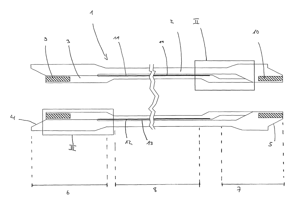
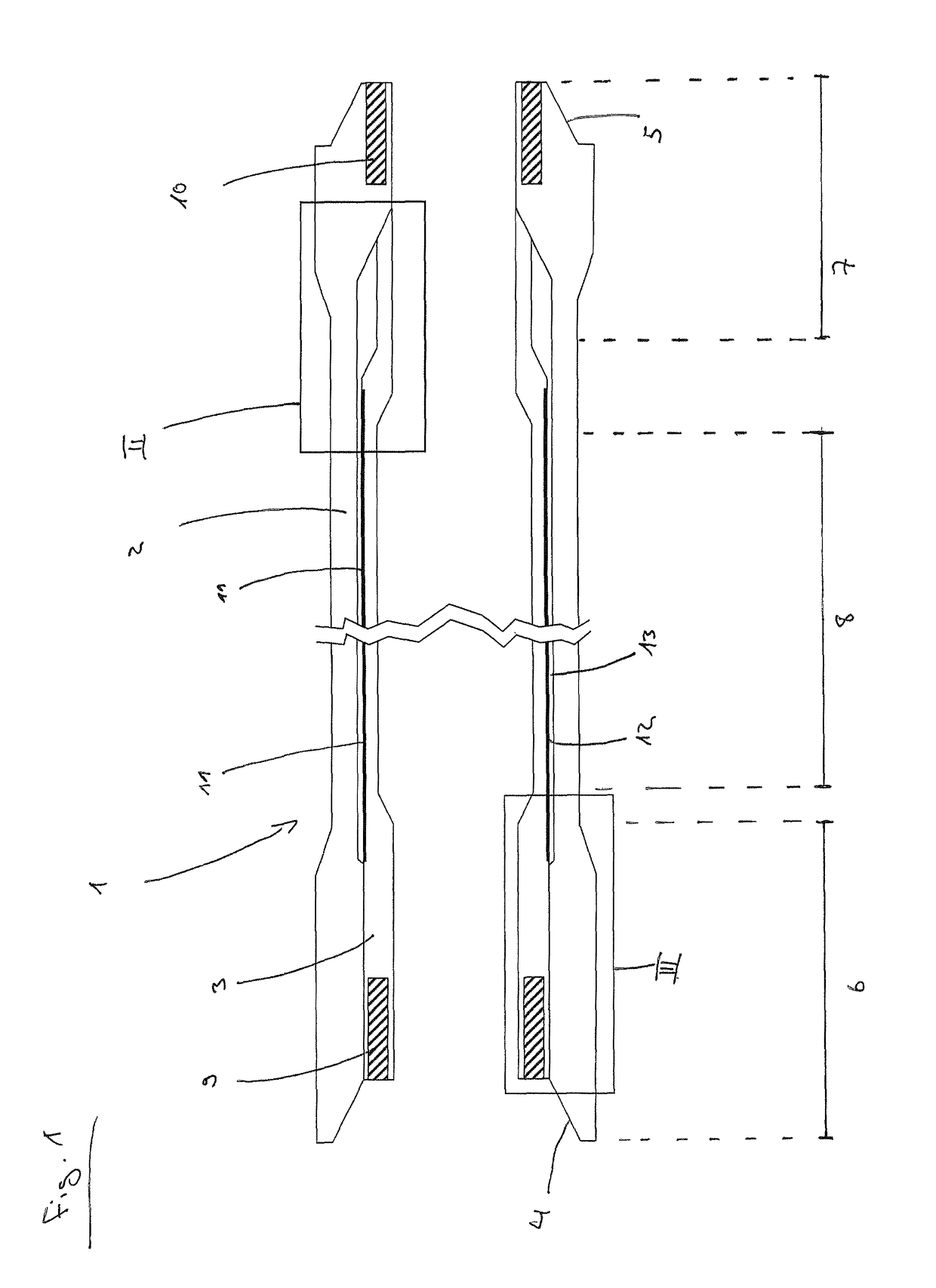
[0018]FIG. 1 shows a greatly simplified sketch of a drill pipe 1 according to the invention with an outer pipe 2 and an inner pipe 3. In a way that is known in the art, the drill pipe has a female connector 4 with an internal thread (not shown) and a male connector 5 with an external thread (not shown). In this case, an end region on the female connector side forms the box region 6, and an end region on the male connector side forms the pin region 7. A center region 8 extends between these two. The pin region 7, the center region 8, and the box region 6 can be manufactured integrally, i.e., in one part, or in multiple parts, for example welded (e.g., by abrasive welding), glued, or screwed.

[0019]In this case, the depicted wall thickness of the inner pipe 3 is used only for illustration. In reality, the goal is that the difference between the inner diameter of the outer pipe 2 and the inner diameter of the inner pipe 3 be as small as possible. The inner diameter of the inner pipe 3 p...


PUM


Abstract

A drill pipe, particularly for a drill string, having an outer and an inner pipe (3), a female connector (4) with an internal thread at one end of the drill pipe (1), and a male connector (5) with an external thread at the end opposite from the female connector (4), wherein the inner pipe (3) is arranged substantially concentrically in the outer pipe (2) and the drill pipe (1) has a center region (8) with an internal diameter. The outer pipe (2) has an inwardly thickened wall portion at an end region (7) on the male connector side, having a smaller internal diameter than the internal diameter of the center region (8), and the internal diameter of the outer pipe (2) remains substantially the same at an end region (6) on the female connector side in relation to the internal diameter of the center region (8).

Description

BACKGROUND OF THE INVENTIONField of the Invention[0001]The invention relates to a drill pipe, in particular for a drill string, with an outer pipe and an inner pipe, a female connector with an internal thread on one end of the drill pipe and a male connector with an external thread on the end opposite to the female connector, whereby the inner pipe is arranged essentially concentrically in the outer pipe and whereby the drill pipe has a center region with an inner diameter.Description of the Related Art[0002]In the case of modern drilling, for example for crude oil, natural gas, or for exploiting geothermics, there are three essential aims in the configuration of drill strings, which aims are in conflict with one another. Thus, it is desirable to provide drill strings with large inner diameters in order to achieve as low a pressure loss as possible for the drilling fluid (mud). At the same time, it is important in terms of safety but also in terms of efficiency to be informed as pre...

Claims


Application Information

Patent Timeline
Patent Type & Authority Patents(United States)
IPC IPC(8): E21B17/00E21B17/02E21B17/042
CPCE21B17/042E21B17/028E21B17/003E21B17/00E21B17/02Y02E10/10
Inventor LAMIK-THONHAUSER, BOUCHRASCHEIBELMASSER, ANTONKOTOV, ANTONFINE, ALEXANDERGUTSCHELHOFER, MANFREDJUD, JOHANNAICHINGER, FLORIAN
Owner THINK & VISION
Why Eureka
Try Eureka