
Articulated reciprocating counterweight

a reciprocating counterweight and articulating technology, applied in the direction of borehole/well accessories, programme control, instruments, etc., can solve the problems of large and expensive machine designed for heavy lifting, unbalanced lowering, significant unresolved net torque, etc., to achieve efficient lifting and lowering loads, the effect of reducing the net torqu

Active Publication Date: 2018-10-23
DREHER GEORGE R
View PDF8 Cites 6 Cited by
  • Summary
  • Abstract
  • Description
  • Claims
  • Application Information

AI Technical Summary

Benefits of technology

The present invention provides a system for lifting and lowering loads more efficiently and economically compared to existing systems. It achieves this by using an extended counterweight that can be moved to a desired position at a desired time to reduce net torque when lifting or lowering an unbalanced load. The counterweight can be adjusted to increase or decrease the counterbalance effect, depending on the requirements for lifting or lowering the load. This leads to better performance and economic benefits, such as longer life for speed reducers and increased efficiency of the load lifting and lowering process.

Problems solved by technology

Machines designed to do heavy lifting are big and expensive and repairs on worn parts are expensive.
The problem is that in beam pumped wells the lifted weight is about 1.5 times the weight of the lowered weight due to lifting the weight of the fluid plus the buoyant weight of the sucker rods in the pipe when lifting, but the fluid weight is then held by the downhole pump standing valve when lowered making lifting and lowering unbalanced, so in known references, the difference in counterweight required is split on the up stroke and down stroke which leaves significant unresolved net torque due to the unsolved unbalanced downhole condition.
But, the air balance design can reverse direction and the gear teeth in the speed reducer are known for long life.
1958 motorized screw adjustable beam mounted counterweight used motor amp readings to adjust to the desired position on the rear of the beam to “balance” the unit but reportedly the inevitable damage to threads on the screw caused problems.
All the designs mentioned can achieve a fairly limited increase in efficiency but still leave the problem of downhole unbalanced weight between lifting and lowering.

Method used


Image

  • Articulated reciprocating counterweight
  • Articulated reciprocating counterweight
  • Articulated reciprocating counterweight

Examples


Embodiment Construction

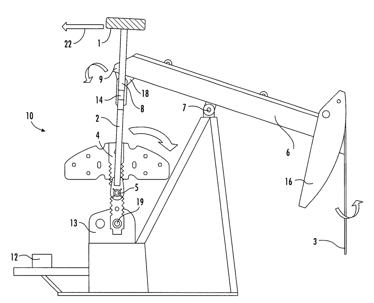
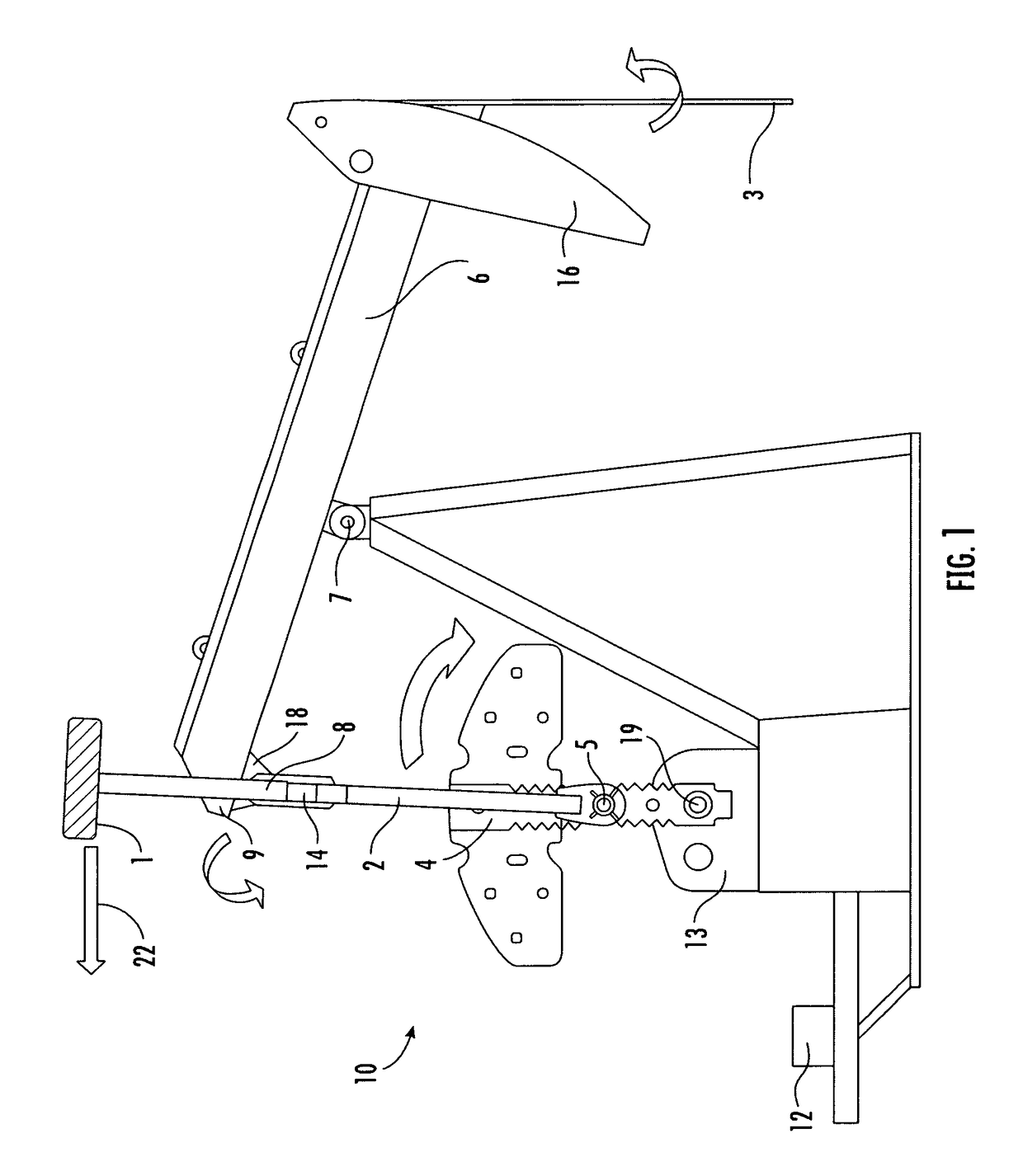
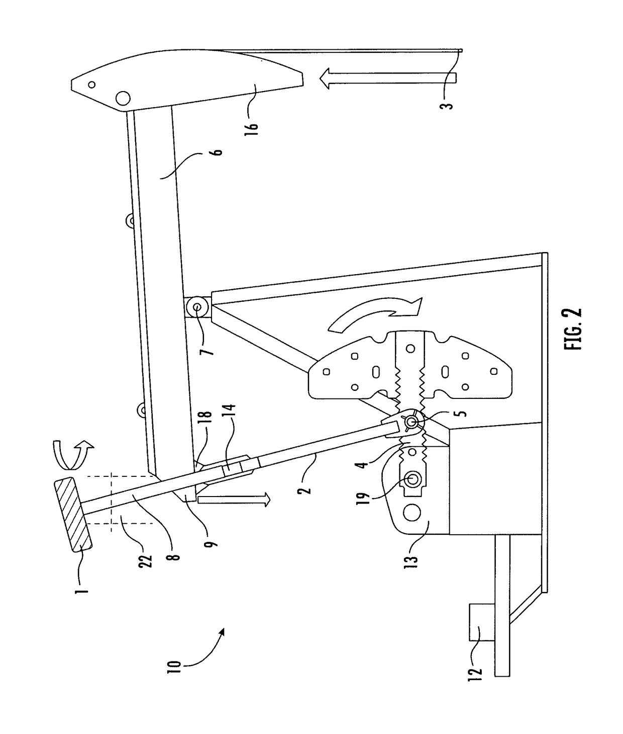
[0015]Embodiments of the present invention relate to lifting and lowering loads more efficiently and also more economically than known systems. This invention is the continuous movement by mechanical means of an extended counterweight to a desired advantageous position at a desired advantageous moment to achieve a desired reduced net torque when lifting or lowering an unbalanced load with a beam with a fulcrum and connected to a load and an effort.

[0016]In one embodiment, a walking beam well pumping unit, the lifting and lowering of the well load can be caused by the reciprocating motion of a beam tipping on a fulcrum counterbalanced with an extended counterweight.

[0017]In one embodiment, when maximum counterweight effect for lifting the unbalanced well load is desired, which occurs at the same time as lowering the crank arm, the extended counterweight is swayed away from the fulcrum thereby increasing the counterbalance effect. Vice versa, when minimum counterbalnce effect for lowe...


PUM


Abstract

A moving counterweight that reduces lifting and lowering torque of an unbalanced load. In one embodiment, a beam pump, an articulated reciprocating counterweight extending above the effort of a class 1 lever on extended pitman arms above the lever effort at the tail bearing to structurally and continuously changes it's position in an air-arc to reduce lifting and lowering torque, by rigid-mechanical geometric re-positioning of the counterbalance effect to and fro, when the rotation is crank arms falling toward the well load, thus mechanically, continuously, favorably, and without friction re-positioning the counterweight either away from the load and fulcrum thereby increasing the counterbalance effect, or nearer to the load and fulcrum thereby decreasing the counterbalance effect, as is desirable to compensate the unbalanced downhole load, where the load in the lift direction exceeds the load in the return direction. The longer the extension of the pitman arm above the beam with the counterweight attached the greater is the counterweight effect of the counterweight deadweight.

Description

CROSS-REFERENCE TO RELATED APPLICATIONS[0001]This application claims priority to and the benefit of the filing of U.S. Provisional Patent Application No. 62 / 411,556, entitled-“POSITION CHANGING EXTENDED COUNTERWEIGHT”, filed on Oct. 22, 2016; U.S. Provisional Patent Application No. 62 / 403,165, filed on Oct. 2, 2016; U.S. Provisional Patent Application No. 62 / 421,410, filed on Nov. 14, 2016; U.S. Provisional Patent Application Ser. No. 62 / 426,337, filed on Nov. 25, 2016; U.S. Provisional Patent Application Ser. No. 62 / 535,846, filed on Jul. 22, 2017; U.S. Provisional Patent Application Ser. No. 62 / 535,945, filed on Jul. 23, 2017; and U.S. Non-Provisional patent application Ser. No. 15 / 719,964, filed on Sep. 29, 2017; and the specifications and claims (if any) thereof are incorporated herein by reference.BACKGROUND OF THE INVENTIONField of the Invention (Technical Field)[0002]Embodiments of the present invention relate generally to improved efficiency for lifting and lowering unbalanc...

Claims


Application Information

Patent Timeline
IPC IPC(8): F04B47/14E21B43/12
CPCF04B47/145E21B43/127F04B47/14E21B47/009G05B19/402G05B19/406G05B2219/31313
Inventor DREHER, GEORGE R
Owner DREHER GEORGE R
Learn More