Optical cable and manufacturing method
a manufacturing method and optical cable technology, applied in the field of optical access networks, can solve the problems of slow manufacturing process, inability to carry out in a single shot, and inconvenient access to fibres, and the cable is more difficult to be installed in the du
- Summary
- Abstract
- Description
- Claims
- Application Information
AI Technical Summary
Benefits of technology
Problems solved by technology
Method used
Image

Examples
first embodiment
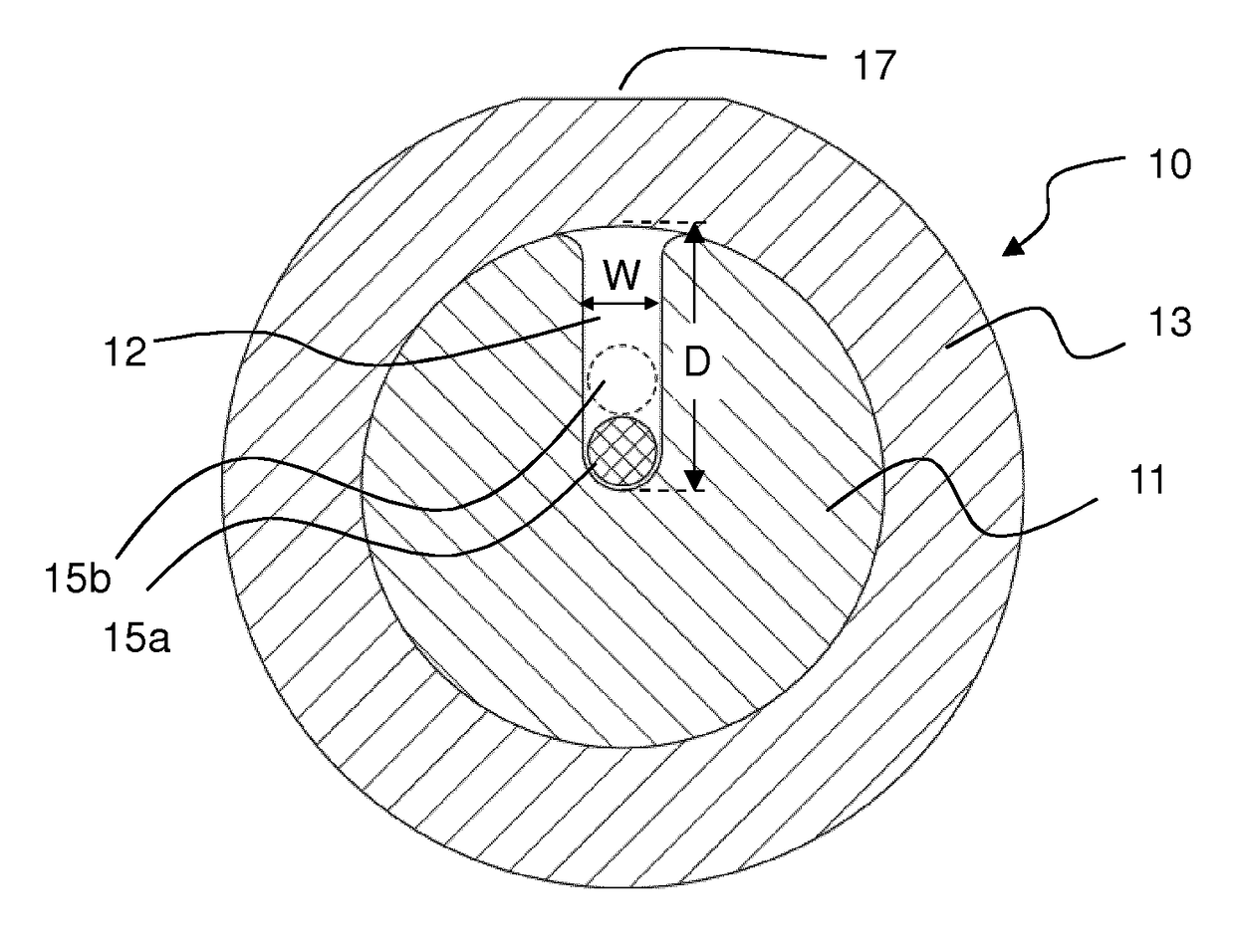
[0057]FIGS. 1a and 1b schematically show an optical cable according to the present invention.
[0058]Cable 10 comprises a load bearing core 11 with a slot 12 where one or more optical fibres 15a, 15b are housed. Cable 10 also preferably comprises a sheath or jacket 13 arranged in an outer position with respect to core 11.
[0059]Load bearing core 11 has preferably a substantially curved-bottom cross-section. Core 11 is preferably made of a fibre reinforced composite material or FRP based, for example, on any of glass fibres, carbon fibres, aramid fibres, poly (p-phenylene-2,6-benzobisoxazole) (PBO) fibres or the like embedded in a polymeric resin. In examples, core 11 is essentially made of glass-reinforced plastic, GRP, with modulus of elasticity of 50 GPa.
[0060]The core 11 can be produced by pultrusion, by UV curing or any other known technique. Pultrusion results in a more regular product.
[0061]Core 11 has preferably a circular cross-section. However, it can have a cross-section diff...
second embodiment
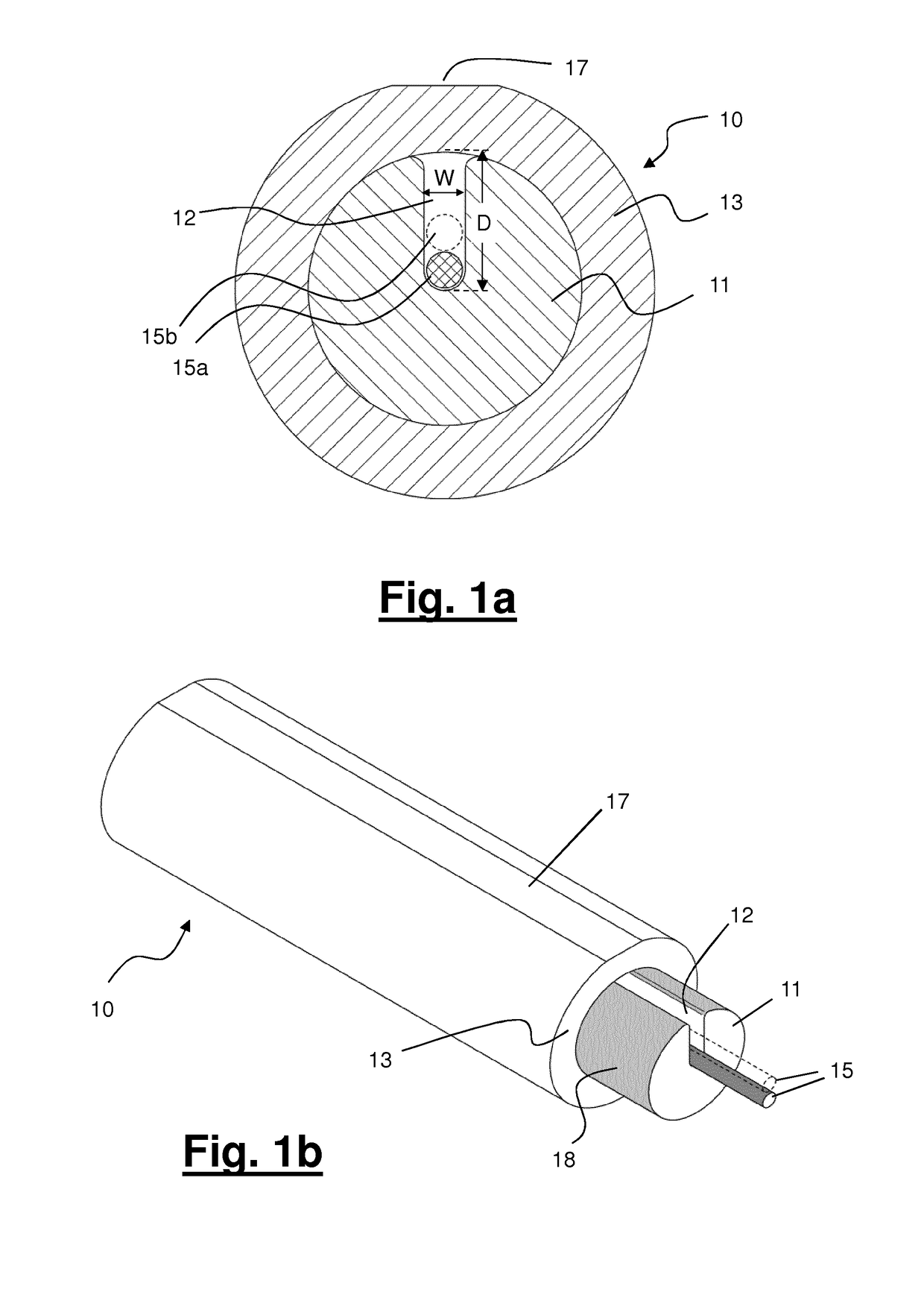
[0086]FIGS. 2a and 2b show the cable according to the present invention. The cable has been designated by reference number 20. The same or similar parts of the cable of the second example have been designated by reference numbers similar to the reference numbers of the first example wherein the first digit is “2” and not “1”.
[0087]The cable 20 of FIGS. 2a, 2b is generally similar to the cable of FIG. 1 and the detailed description will not be repeated. The difference is that the cable 20 further comprises two reinforcing elements 24. Preferably, the centre of each reinforcing element lies in a plane perpendicular to the depth D of the slot 22. Preferably, each of the reinforcing elements 24 is at the same distance from the centre of the load bearing core 21.
[0088]Reinforcing elements 24 can be in the form of a couple of rods or yarns. They can comprise aramid yarns or glass fibres.
[0089]Reinforcing elements 24 can have a diameter of from 0.3 to 1 mm.
[0090]Profitably, a thin polymeri...
third embodiment
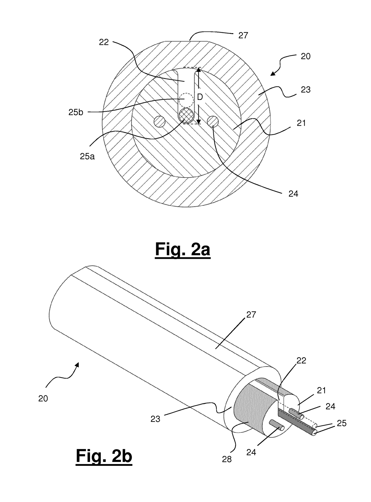
[0091]FIGS. 3a and 3b show the cable according to the present invention. The cable has been designated by reference number 30. The same or similar parts of the cable of the third example have been designated by reference numbers similar to the reference numbers of the first example wherein the first digit is “3” and not “1”.
[0092]The cable 30 of FIGS. 3a, 3b is generally similar to the cable of FIG. 1 and the detailed description will not be repeated. The difference is that the cable 30 further two reinforcing elements 34. Preferably, the centre of each reinforcing element 34 lies in a plane perpendicular to the depth D of the slot 32. Preferably, each of the reinforcing elements 34 is at the same distance from the centre of the load bearing core 31.
[0093]Reinforcing elements 34 can be in the form of a couple of rods or yarns. They can comprise aramid yarns or glass fibres.
[0094]Reinforcing elements 34 can have a diameter of from 0.3 to 1 mm.
[0095]Profitably, a thin polymeric layer ...
PUM
 Abstract
Description
Claims
Application Information
 - R&D
- Intellectual Property
- Life Sciences
- Materials
- Tech Scout
- Unparalleled Data Quality
- Higher Quality Content
- 60% Fewer Hallucinations
Browse by: Latest US Patents, China's latest patents, Technical Efficacy Thesaurus, Application Domain, Technology Topic, Popular Technical Reports.
© 2025 PatSnap. All rights reserved.Legal|Privacy policy|Modern Slavery Act Transparency Statement|Sitemap|About US| Contact US: help@patsnap.com