Group of blade rows

a blade row and row group technology, applied in the direction of machines/engines, machines/engines, stators, etc., can solve the problems of limited aerodynamic loadability and fluid-flow machine efficiency, unsuitable design rules for individual blade rows, and unfavorable flow behaviour, etc., to achieve favorable flow behaviour

Active Publication Date: 2018-10-30
ROLLS ROYCE DEUT LTD & CO KG
View PDF21 Cites 2 Cited by
  • Summary
  • Abstract
  • Description
  • Claims
  • Application Information

AI Technical Summary

Benefits of technology

[0008]An object underlying the present invention is to provide a blade row group that achieves a favourable flow behaviour due to the fixing of different profile depths of two adjacent member blade rows both in the center area and in the edge areas of the main flow path.

Problems solved by technology

The aerodynamic loadability and the efficiency of fluid-flow machines, in particular blowers, compressors, turbines, pumps and fans, is limited by the growth and the separation of boundary layers near and on the hub and casing walls.
The problems in the edge areas are primarily due to the fact that the favourable arrangement of two adjacent blade edges of a blade row group in the center of the main flow path has an unfavourable effect in the vicinity of the flow path boundary.
Also, design rules known from individual blade rows are not applicable.
It cannot therefore clearly describe the shape of the blade edges, and accordingly cannot solve the aerodynamic problem of achieving an advantageous effect on the flow.

Method used


Image

  • Group of blade rows
  • Group of blade rows
  • Group of blade rows

Examples


Embodiment Construction

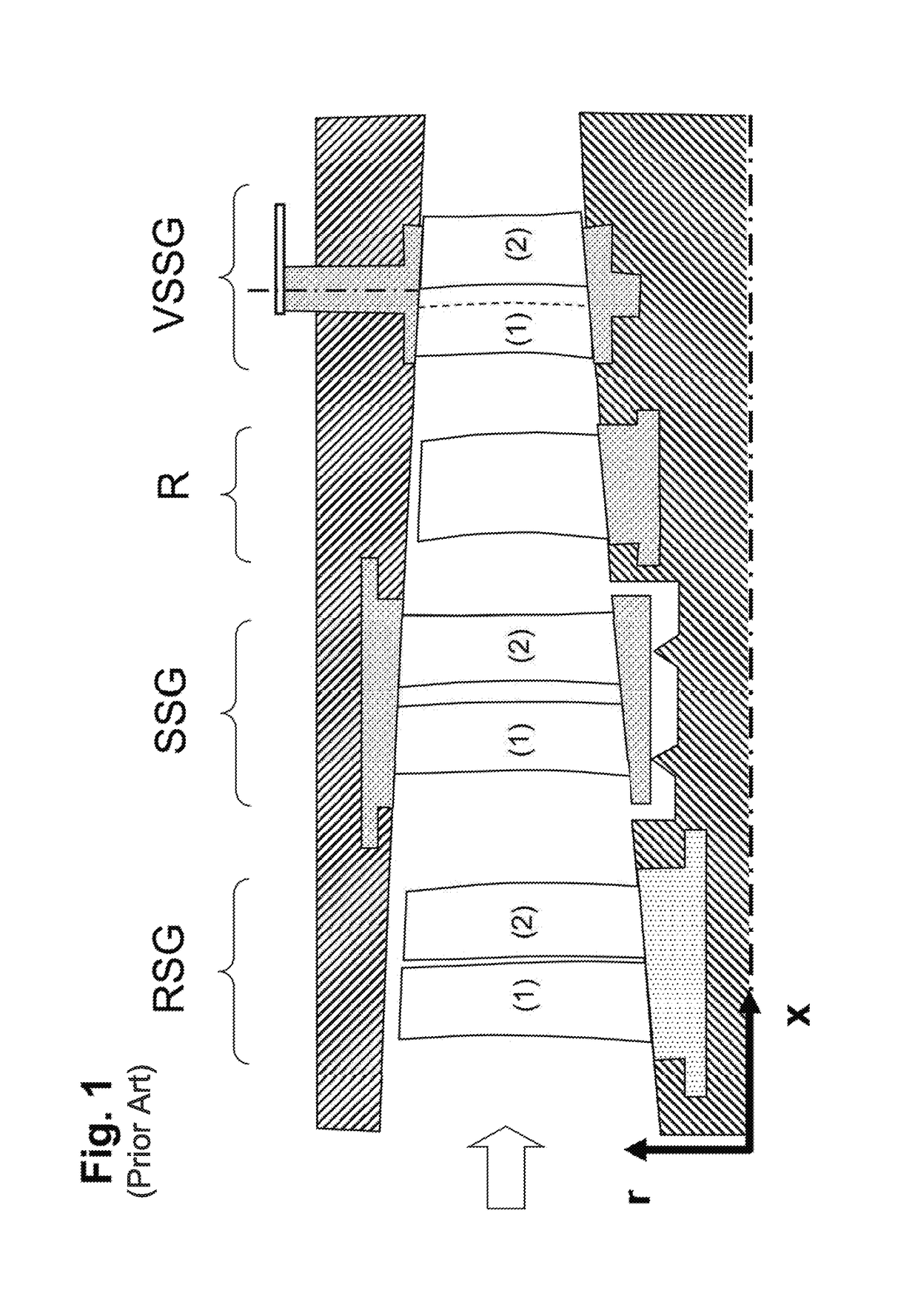
[0024]A conventional blade row group according to the state of the art, as shown in FIG. 1, has no special features in respect of a specific variation of the profile depth. In particular, there is no special shape of the four blade edges arising from profile depth variations. There are no further design features which can be innovatively developed by a more complex exploitation of the arrangement as a blade group. A blade row group as considered here has, unlike an individual blade row, a relatively far higher load on the side wall boundary layers, which has to be compensated for by specific additional measures. An excess of profile depth in the area of the blade ends under the specific aerodynamic effect of an arrangement as a blade row group is therefore a way to extend the operating range of blade row groups.

[0025]FIG. 1 shows, in the meridional plane established by the axial direction x and the radial direction r, several blade row groups, with each of the blade row groups inclu...


PUM


Abstract

The present invention relates to a blade row group arrangeable in a main flow path of a fluid-flow machine and including N adjacent member blade rows firmly arranged relative to one another in both the meridional direction (m) and the circumferential direction (u), with the number N of the member blade rows being greater than / equal to 2 and (i) designating the running index with values between 1 and N. Here, a front member blade row with front blades (i) having a leading edge and a trailing edge as well as a rear member blade row with rear blades (i+1) having a leading edge and a trailing edge are provided.

Description

CROSS-REFERENCE TO RELATED APPLICATION[0001]This application claims priority to German Patent Application No. 10 2014 203 604.6 filed on Feb. 27, 2014, the entirety of which is incorporated by reference herein.BACKGROUND[0002]This invention relates to a blade row group.[0003]The aerodynamic loadability and the efficiency of fluid-flow machines, in particular blowers, compressors, turbines, pumps and fans, is limited by the growth and the separation of boundary layers near and on the hub and casing walls. To remedy this problem in the case of high aerodynamic loading and important boundary layer growth on the annulus duct side walls (hub or casing), the state of the art provides solutions only to a limited extent.[0004]State of the art in fluid-flow machines are arrangements with double-row stator wheels, usually employed as exit stator wheels in compressors, or also double-row rotor arrangements in which directly adjacent rotors operate counter-rotatingly, or in which two directly a...

Claims


Application Information

Patent Timeline
Patent Type & Authority Patents(United States)
IPC IPC(8): F01D5/06F04D29/54F04D29/32F04D19/00F01D9/04F01D5/14
CPCF01D5/142F01D5/06F01D5/146F01D9/041F04D29/324F04D29/544F04D19/002Y02T50/673F05D2240/40F05D2270/17Y02T50/60
Inventor GUEMMER, VOLKER
Owner ROLLS ROYCE DEUT LTD & CO KG
Why Eureka
Try Eureka