Method and magnetic resonance system for detecting MR data

a magnetic resonance system and data detection technology, applied in the field of methods and magnetic resonance systems, can solve the problems of reducing the detection efficiency of mr data, and clearly too long for clinical protocols, so as to reduce the problem caused

Inactive Publication Date: 2018-10-30
SIEMENS HEALTHCARE GMBH
View PDF10 Cites 0 Cited by
  • Summary
  • Abstract
  • Description
  • Claims
  • Application Information

AI Technical Summary

Benefits of technology

[0007]An object of the present invention is to reduce the problems caused by the extreme stress.
[0019]According to a second variant, the above-described substeps for the detection of the multiple k-space lines are performed with the second phase encoding gradient in each case being activated along the second direction before the respective switching activation the readout gradient, and hence before the detection of the MR data of the respective k-space line of the multiple k-space lines. In other words, with the second variant, compared to the prior art, activation of the second phase encoding gradient after the respective detection of one of the multiple k-space lines is less frequent, which almost cancels the effect of the respective k-space line before the detection of those lines by the activation of the second phase encoding gradient.
[0026]Because the relatively long first phase encoding gradient, which is used for SEMAC encoding, is no longer activated in the echo train (i.e. no longer during the processing of the above-described substeps), the other gradients (in particular the second phase encoding gradient) move closer together chronologically as a result of which the so-called ESP (echo spacing, i.e. the distance between two chronologically adjacent echoes) can be reduced, thus resulting in improved image quality and a reduction in the recording time.
[0031]Compared to the prior art, the present invention has lower gradient stress and hence fewer duty cycle problems and less heating and on the other hand permits chronological optimization of the recording procedure which has a positive effect on image quality.

Problems solved by technology

If eight SEMAC steps are used to suppress metal artifacts, the measuring time increases to more than 17 minutes, which is clearly too long for clinical protocols.
This long measuring time places significant stress on the gradient system of the magnetic resonance system, which can disadvantageously result in a limit defined, for example, by the duty cycle (for example defined by a percentage with which the first phase encoding gradient is switched over time) being exceeded.

Method used


Image

  • Method and magnetic resonance system for detecting MR data
  • Method and magnetic resonance system for detecting MR data
  • Method and magnetic resonance system for detecting MR data

Examples


Embodiment Construction

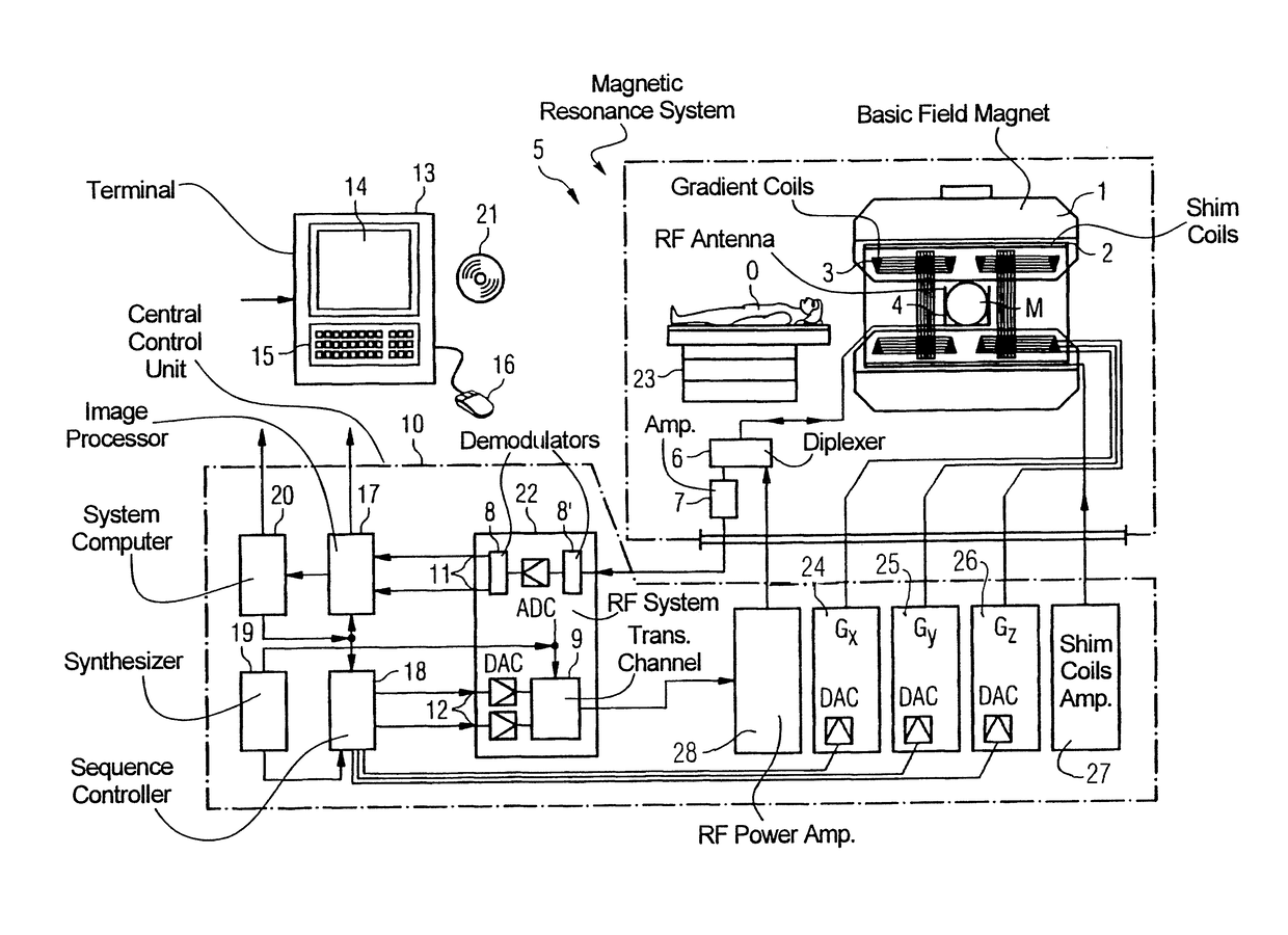
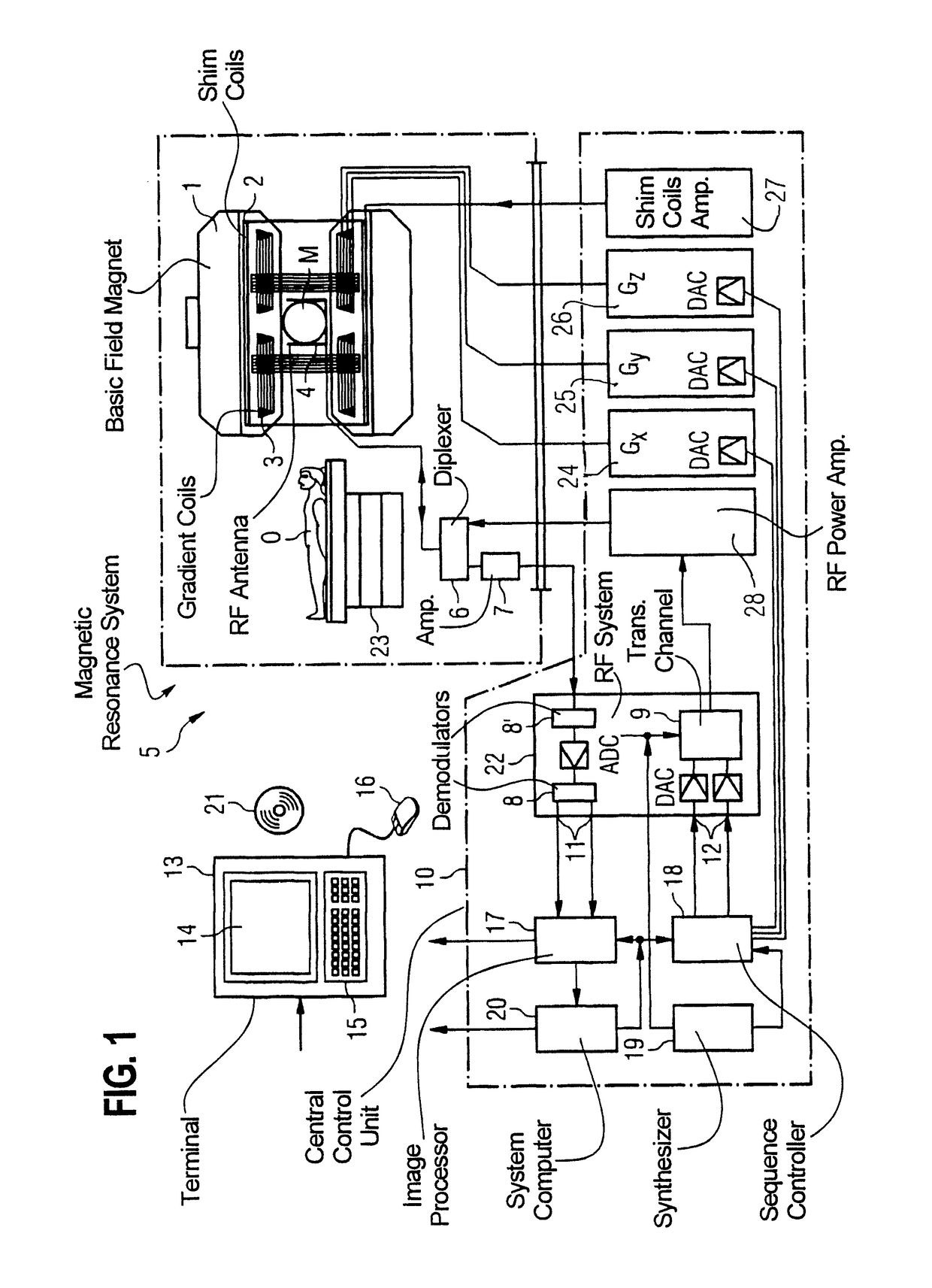
[0038]FIG. 1 is a schematic diagram of a magnetic resonance system according to the invention 5 (of a magnetic resonance imaging device or computed tomography device). In this context, a basic field magnet 1 of the scanner generates a chronologically constant strong magnetic field for the polarization or alignment of the nuclear spins in an area to be examined of an object O, such as, for example, a part of a human body to be examined. The object O, lying on a table 23, is continuously pushed into the magnetic resonance system 5. The high degree of homogeneity required for the nuclear spin resonance measurement of the basic magnetic field is defined in a typically spherical measuring volume M through which the parts of the human body to be examined are continuously moved. To support the requirements for homogeneity and in particular to eliminate chronologically invariable influences, so-called shim plates made of ferromagnetic material are attached at a suitable location. Chronologi...


PUM


Abstract

In a method and apparatus for detecting magnetic resonance (MR) data a slice is slice-selectively excited followed by irradiation of a refocusing pulse and activation of first and second phase encoding gradients, and a readout gradient, in order to read out MR data that are entered into a line of k-space. MR data for further multiple lines of k-space are acquired without the first phase encoding gradient being activated again, and follow radiation of another refocusing pulse.

Description

BACKGROUND OF THE INVENTION[0001]Field of the Invention[0002]The present invention concerns a method and a magnetic resonance system to detect MR data of a predetermined volume portion of an object under examination, particularly in the case of magnetic field inhomogeneities.[0003]Description of the Prior Art[0004]A SEMAC method can be used to suppress metal artifacts in SE (spin echo)-based magnetic resonance data acquisition sequences (for example TSE (turbo spin echo)), see “SEMAC: Slice Encoding for Metal Artifact Correction in MRI”, W. Lu et al. Magnetic Resonance In Medicine 62, pages 66-76, 2009. In this context, with a conventional two-dimensional protocol or slice-by-slice excitation, additional encoding is performed in the slice direction. This encoding corresponds to phase encoding and is also known as so-called SEMAC encoding. In this context, the measuring time increases linearly with the number of additional phase encoding steps in the slice-selection direction, which ...

Claims


Application Information

Patent Timeline
Patent Type & Authority Patents(United States)
IPC IPC(8): G01R33/48G01R33/483G01R33/565G01R33/561
CPCG01R33/4818G01R33/482G01R33/56563G01R33/5617G01R33/4833
Inventor PAUL, DOMINIK
Owner SIEMENS HEALTHCARE GMBH
Why Eureka
Try Eureka